
Tesla Coil
4 inch diameter, 4 foot sparks 2003
The
internet changed everything and next came 4 MOT's (microwave
oven transformers) under oil with an angle grinder
ARSG (asynchronous rotary spark gap) on a 4 x 23 inch
coil using a polyethylene/oil capacitor in a 6 inch PVC for around 4 ft sparks.
 (click to enlarge)
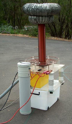
The TC in daylight (above). The capacitor is the upright white cylinder, the yellow
box is the ARSG, the brown upright is the secondary coil and the double
toroid is on top.
Primary:
1/4 inch copper piping wound to 11 turns on acrylic supports.
Tapped at around 4 turns for a 48 nF tank capacitor. This
gets quite warm in action after only a few minutes, particularly the innermost turns.
Secondary:
648 turns of
19 G (0.81
mm = 0.0335 inch) enamelled wire taking up 24 inches on 4 1/2 inch PVC pipe.
The 10.5 turn/cm (27 turns/inch) gives a winding wire width of 0.851 mm
(0.0345 inch) giving a 97% winding percentage . Coated with several coats of spray on
polyurethane sealer.
This retains a bit of a surface static charge after use and can
give small sparks onto your hands near the top of the coil. I have had
to remove 2 turns in three different places due to breakdowns after
quite some use. They all occurred several inches from the base. The PVC
former has acrylic end caps and one ventilation hole as I used PVC
solvent based glues. (This is a no-no because of explosion risk. Non
solvent based glues such as epoxy are preferred). I have used a PVC
screw in base to allow dismantling. I've now wound a second identical
coil as a spare prior to my school display as I was worried about
further breakdowns. Measured resonant frequency is 297 kHz.
Tank capacitor
"rolled poly": 2002
The photo
at the top of the page shows a 35 nF capacitor made from polyethylene and aluminium foil rolled
and immersed in transformer
oil. I didn't vacuum seal these and the lid unscrews. They are 6 x
24 inches
mounted vertically. They are mostly filled with low viscosity
naphthenic transformer oil
(A$70 for 20 litres) allows free bubbling out of air particularly in the
rather loose z folding. I used a z folding approach to minimise
inductance and this has given the hottest sparks on this system.
At these powers and with the very thin dielectric 4 mils x 4 this
capacitor didn't last too long. Other capacitors I have used were rolled
not z folded and ranged from 15 to 48 nF with
progressive increase in power and heat generation in all
primary circuit wiring. The 1/2 inch steel bolts from the capacitor got
hot enough after less than 1 minute with 48 nF to give me a significant
burn. They probably had rather high RF hysteresis losses and have
subsequently been replaced with brass ones which run much cooler.

 (click to enlarge)
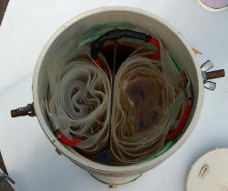
My
best and longest lived Tesla coil capacitor is 48 nF constructed with 2 in series internally with
(as I recall) only 2 layers of 4 mils each. This has lasted longer than
single capacitors with 10 layers of 4 mils each. The right photo
shows the two separate capacitors wired internally. Note that only
one of these capacitors is still running after 2 years which is the 6 nF
one in the right of the group photo. It has been used up to almost
50 kV but not in Tesla coil duty.
Toroid
The double toroid is 6 inch
air conditioning duct with the lower one being 15 inches and the upper
24 inches diameter. It has been a bit smoothed with aluminium tape.
It is well behaved and I have not had any problems with top of secondary
coil breakout.
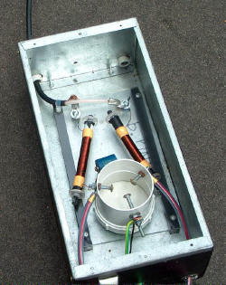
Power supply
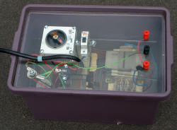
The power supply (below) is made of 4 MOT's
(microwave oven transformers) in transformer oil in a plastic container.
This takes 250 V up to 8 kV. Not fancy but cheap. Each 2 kV secondary
is in series
and each 250 V primary is in parallel. There are a 20 A circuit
breaker, 20 A key switch and an earth point mounted on an acrylic sheet
which sits on an internal lip. There is also limited power factor correction capacitors (30 uF polypropylene
but needs more) and microwave oven
suppression circuitry. This has been most reliable. I was
concerned about explosion risk if a spark occurred in the air space,
however, this has occurred without any problem and the transformer oil
seems to be of low volatility.
 (click to enlarge)
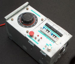
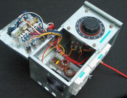
The variac control box
The variac control box (below) is fan cooled and the variac
is rated at 15 A 240 V.
I have run this at higher powers with no discernible heating. It is mounted in a galvanised iron domestic meter box. It has
various cutouts including RCD's (residual current devices) on the variac
and direct circuits. There are meters for variac output voltage and
current as well as total current. I also have included a series circuit
which can switch in a ballast resistance (such as a fan heater),
or inductance (such as a shorted MOT). The direct mains line has a triac controller for
variable speed for my ARSG motor. I have blown this twice and have
replaced this with a limiting inductor. Current draw with 32 nF tank capacitor is about 15 A 250 V in with the variac at about 180 V.
It goes hard off scale at 20 A when on full although for short runs
doesn't trip the 20 A breakers. Current draw is higher with a total of
92 nF tank cap.
 (click to enlarge)
Filter
circuit
The filter circuit is to prevent high voltages coming back to the main
transformer. This is particularly important when using NST's which
are rather fragile with respect to overvoltage. It is inserted
between the main transformer and the primary circuit (tank cap, spark
gap and primary coil).
 (click to enlarge)
The left photo shows the old version with 2 ferrite core
inductors shunted on the MOT side by a ceramic capacitor rated at 570 pF 40 kV.
They recently arced over and blew an inch off the ends of the ferrite
rods. There is a safety gap set to a
rather wide 1 inch. If this fires there is a big
flaming arc that doesn't extinguish. All this is rather old fashioned
and has been shown to be ineffective. The upgrade in the right
photo uses a more
sophisticated "Terry filter" with MOV's (metal oxide varistors)
resistors and capacitors and are far better at protecting neon sign
transformers. The safety gap is set much closer and it is set so
it just doesn't fire when connected to the transformer alone. In
operation there will be resonant voltage rise but also voltage drop
under load so this seems to be the right level.
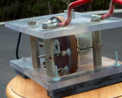
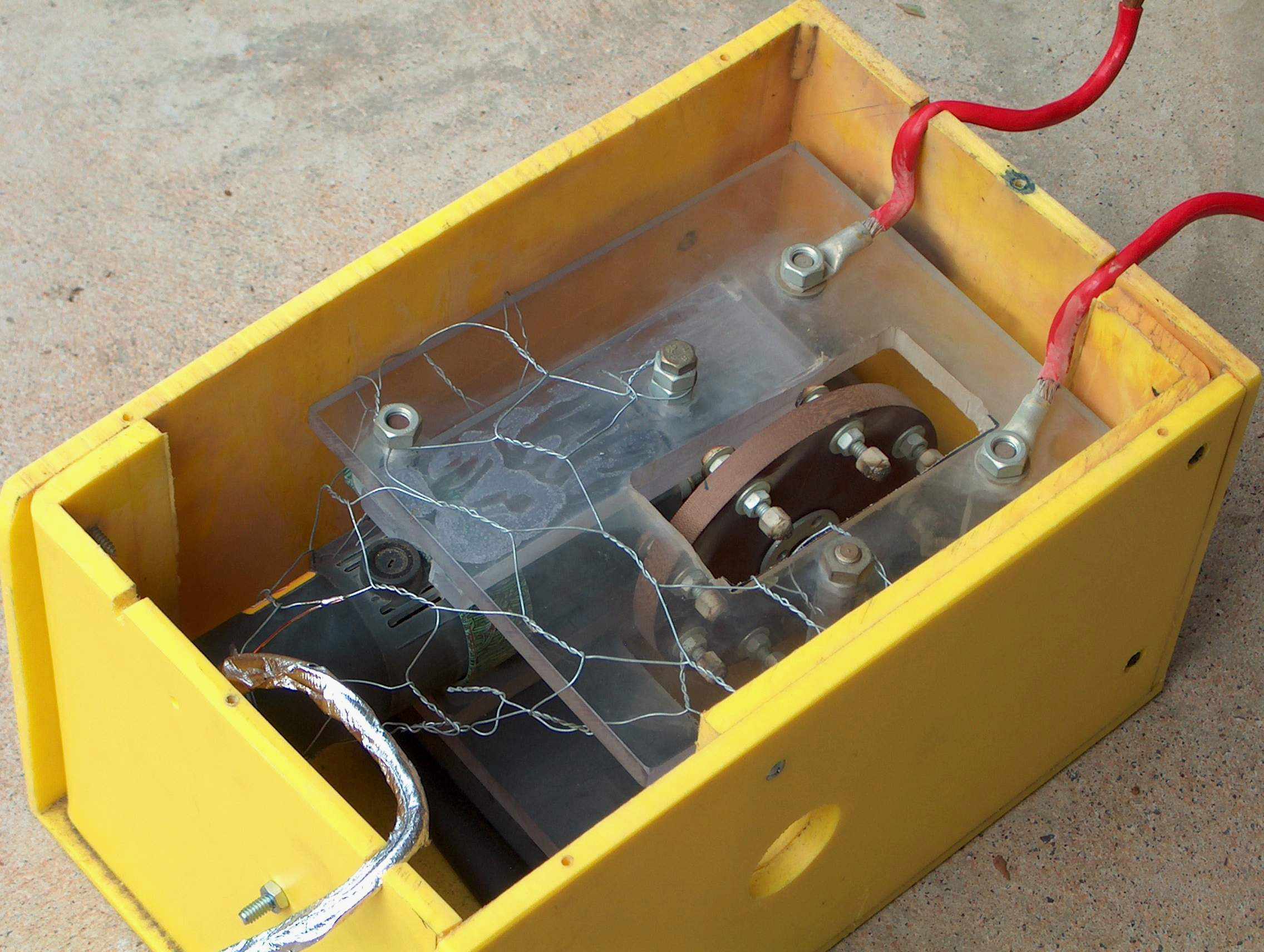
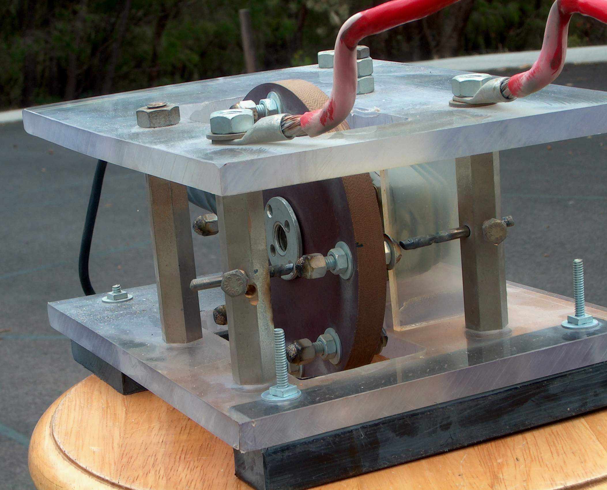
Spark gap
The spark gap
(below) is an ARSG (asynchronous rotary spark gap) using a 500 W angle
grinder of a nominal 11,000 RPM . This has been measured in the
current setup at 9,000 RPM = 150 RPS which gives giving a fairly high
1200 bps (breaks per second). This is a lot higher than other
ARSG's that often run around 400 bps.
The disc is 1/2 in. thick made of
Tufnol
with 8 x 1/4 in. steel bolts. Tufnol is a high pressure laminate and has been used by
others
for this purpose. It is much stronger and temperature resistant
than my previous polycarbonate wheels which were prone to cracking or
creeping of the outer electrodes at highest power levels. The stationary electrodes are
3/16 inch 2% thoriated tungsten. The tungsten rods wear down and require
adjusting perhaps every 15 - 30 mins of use. Cooling is with the
angle grinder fan and when needed, I now use a garden leaf blower as
well. This is not ideal as the blower motor (1100 W) is cooled by
that airflow so it is actually delivering warm air although in large
volumes. Added to the angle grinder 500 W and the spark gap ?500 - 1000
W gives over 2 kW that has to be air cooled. The ARSG
is enclosed in a solid thick polypropylene box and the top is acrylic
with large ventilation holes but is also protected by the Tesla coil
acrylic base a few inches above it. I have some token shielding which is
grounded but keep tripping my RCD's when I get a strike to the ground
rail.

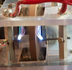
(click to enlarge)
The third photo above with the sparks was taken with 4 kV direct
from the power supply giving a mild spark for ease of photography. In
action with the capacitors running the Tesla coil it is blindingly
bright.
Wiring
Wiring is with 4-8 mm automotive cable which gets hot. I was using a
large alligator clip to tap the primary and the solder melted. The
magnetic steel in the alligator clip was responsible resulting in
radio frequency hysteresis losses.


