
Ionic spinners
2007
Also known as electrostatic corona motors. This is an ionic wind powered
device that makes a small wire device rotate when connected to high voltage.
I will post details of a small one and video soon.
Best results are with DC high voltage. To demonstrate this a 14 foot
(4.2 m) spinner cannot be turned by a Tesla coil making 2 foot sparks (100
kHz AC) but can be turned by a DC supply running perhaps 60kV with 3 inch
sparks.
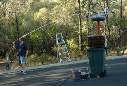
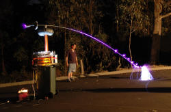
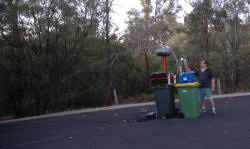 (click
to enlarge)
The left photo above shows the 14 foot (4.2 m) arm that turns on a 1
mm shaft and has low enough friction to drift in the wind. The
center photo shows the Tesla coil and the corona from the shaped tip and
multiple breakout points in this 14 second exposure. The Tesla coil
did not move it. The right photo shows the rod electrically
disconnected from the Tesla coil which is off. I have hooked up my 60 kV
supply and on this time exposure of 36 seconds you can see the rod has
rotated through at least 180 degrees (see the faint rod above my head which
is briefly lit by the sparks that I made as it passed).
This lack of performance by a large TC was unexpected. My explanation as to
why a large one doesn't work, but a small one does, is due to the rectifying
effects of different shaped electrodes. Spark length can vary by a
factor of up to three based on my past experiments from a needle point to a
plane depending on which way around the polarity is (negative needle
electrodes give the longest corona). Hence a small streamer from needle points will
ionize a larger volume of air in one polarity than the other due to it's
diode like effect. A mass movement of air can then take place from the
excess of a single charge and thrust occur. With a larger TC, however,
the large streamers can reach a large area well out of the sphere of
influence of needle points and charge accumulation does not occur. To
demonstrate this, your hair does not stand on end if you are near a large TC
but does with much smaller DC voltages.
Now if I had a big diode in line with the corona point then it should work.
500kV high speed diodes however are not cheap. I need to give this more
thought.
Others have run
these on small Tesla coils however.
Lifters
1 2003 (ionic
wind powered device) These are a nifty thing
to do high voltage. In essence they are devices that levitate using ion wind
created from a DC high voltage external source.
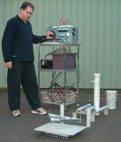
 (click
to enlarge)
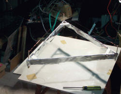
In my Lifter Mk 1 (which is a typical beginners one) a 40 cm triangular ultra light
basla, aluminium foil and wire creation lifts up once around 40kV is
applied. A thin wire supported by balsa wood struts is the source of the
corona and the foil below is attached to the other polarity (positive or
negative). The supply wires are not clearly seen since they get very
agitated with the high voltages. The structure is tethered with cotton
taped to the base. There is occasional arcing across the 3cm between
the top wire and the foil at this voltage. My high voltage source is
the x-ray transformer described below run off a variac. The typical
output used is 30 kV AC which with the addition of a 290 kV diode and
capacitor gives a smoothed, half wave rectified output around 40 kV DC. I have also used
the 100 k ohm resistor
in series to reduce destructive arcing as it burns out the wire.

Lifters 2
2004
 (click
to enlarge)
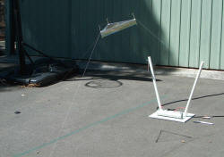
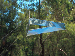
This is Lifter Mk 2 which is a much better flier. Smaller at 6 inches
(15 cm) per side, stronger and a more generous spacing between the foil and
the corona wire. It is powered by a dedicated 30 kV DC stabilized
power supply with one side referenced to earth which means no more sparks
from foil to ground. I use a 100 kohm resistor as above. The
height is limited by the wind outdoors.
 (click to enlarge)
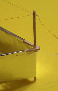
Some detail of one vertex of the triangular lifter showing the recession of
the foil and hot glue construction. Note that the upper wire needs to
have the enamel stripped off at least partly but preferably left on the
support wires to the HV source.
The ionic wind is enough to blow out a flame underneath the lifter and can
be felt. This form of propulsion is similar in principle to the ion
engine used to power
Deep Space 1
spacecraft which used on board Xenon. A normal lifter
will not work in a
vacuum. A comparison of the two.
Deep Space 1
Power:
1280 volts, 2500 W from solar cells
Propellant: stored Xenon gas
ionised to Xe +
Speed:
100,000 kph
Thrust:
9 grams (very low but efficient and can go for years)
Cost:
$200 million
Lifter
Power:
30,000 volts, 5 W
Propellant: air ionised to O+,
N+
Speed:
? 5 kph
Thrust:
3 grams (just enough to lift the very light structure)
Cost:
$1000 for full display (actually only $2 for the lifter itself)
This is a
NASA
scientific publication showing no performance in a vacuum and that the
principle of operation is due to air ionisation.
Others have made lifters large enough to have a small payload such as a
mouse.
A
Japanese lifter is 15 ft (5 m) in diameter and is shown lifting to 45 ft
(15 m).


Lifters 3
Aug 2004
Lifter Mk 3 was developed for a public display. It has custom argon tubes for the upright high
voltage wire supports. In addition it has small neon indicator globes
at the corners of the lifter itself. Very impressive at night. Not
really a high flier however due to the reduced voltage available after the
argons plus the added weight of the small neon tubes. One further
feature is the "Crash land" button. This uses a motorized switch to
short circuit the power supply. This causes a loud and bright spark
visible low down between the upright argons in the left picture, the tall
argons flash and the lifter loses power and falls. Kids (of all ages)
love this one.
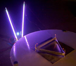
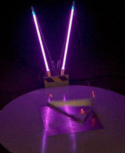
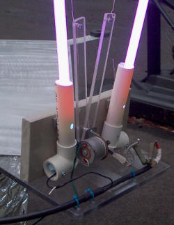
(click to enlarge)
I have measurements of the plain vanilla lifter (i.e. no attached neon's)
which is a 30 cm triangle. This jumps up very smartly to its tether
limit at 2 feet.
Input
24 V 0.80 A = 19 W
Output (measured after argons).
no load (argons only but no wires to lifter) ?30 kV 100 uA
plus HV Meter (100 uA FSD movement) 28 kV 130 uA = 3.6
W
plus lifter (no dropping resistor) 22 kV
400 uA = 8.8 W
Threshold for lift is 14 kV.
Hence net current is around 270 uA and net power used by lifter is around 5
W.
The argon tubes drop about 500 V each with the load of the lifter i.e. about
1 kV is lost. (but gain about 50 kV of coolness)
My lifter, give or take, uses 5 W to lift its 3 g (= 0.6 g/W).
This neat little
helicopter weighs about 2500 kG, and lifts a further 2500 kg using 1 MW.
Proportionately 1MW would lift 600 kg with my lifter specs. Only about 1/4
that needed to achieve lift of the helicopter. One wonders if
technology can't offer something more efficient than my triangular lifter
though. I have a few ideas .....
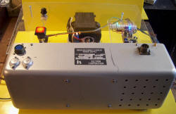 (click to enlarge)
This is the power supply setup using a 30 kV DC regulated supply from a 24 V
transformer and a small PWM (pulse width modulated) controller.
This will be used for the public display lifter soon to be completed.
It does not like repeated short circuits (and tends to blow the 2N3055
drivers) but this has been fixed by using a series resistance (12 kohm 5 W
plus 15 kohm 5 W in series). This weakens the "Crash landing" spark
which then had to be boosted with a 570 pF 40 kV doorknob capacitor.
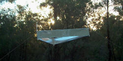
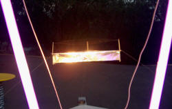 (click to enlarge)
The left photo above is a sunset shot and the right photo shows a view between the
argon tubes. I have highlighted the lifter separately. With this shot you
can see the range of vibration of the first order harmonic of the closest
wire which is about 1 inch in amplitude. If the tension is a little higher or humidity a
bit less, this changes to a second order harmonic with a node in the
middle. I guess this would be preferred as excursion is less, however the
lift will be more as the wire gets closer and if there is an inverse square
law then it may even be helpful.
My balsa supports started to track sparks and carbonize as the humidity
picked up this evening. This is a prelude to a crash and burn. In
desperation I used a light oil spray on the balsa supporting the upper wire
which seems to have worked fine.
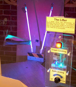 (click to enlarge)
This shows the transparent control panel exposing the electronics of the PWM.
The two controls are a red "Crash landing" control and a rotary "Soft
landing" control. The right picture shows the lifter in the acrylic display during testing.
I am concerned by the radio frequency interference on both AM (~1 Mhz) and FM
(~100 Mhz).
There is no problem open circuit and the DC HV wire is shielded up to the
upright argon tubes which serve as supports for the HV wire. Shorting the
argon tubes does not seem to make a difference. I have tried a ferrite cored
coil in series with the active lead with and without a resistor (330 K)
although the latter does decrease performance. The sealed 30 kV HV unit
is driven by a switch mode supply. This supply is giving minimal RF
interference as a whine which I think I have fixed by putting a suppression
circuit in the 24 VDC line. Some of the RF was corrected with a better
connection to the 2x2 ft ground plane. Unfortunately correcting the RF
at its presumed source, the corona from the upper wires, is not feasible due
to weight constraints.
I recently had to display the lifter within a few feet of a large plasma
display monitor fortunately without problems. Interestingly, in the
final version of the lifter, I did not remove the enamel from the support
wires which means that they are a lot less agitated and give a lot less RF
interference. I have also wound the support wires into a loosely
spaced coil of about 10 turns around the last 6 inches of the argons to try
to help block RF but I am uncertain if it helps.
The lifter has now (Nov 5th 2004) been installed at the
Gravity Discovery
Centre in a 1.5 m square acrylic enclosure. This is the public interface
to the gravity wave detector under development here in Western Australia.
Still running in May 2006 with periodic replacements of the lifter and
repair of fractured and oxidized wires.
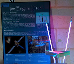
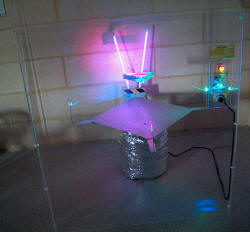 (click to enlarge)
The left picture shows the display poster. The right picture shows the
full installation running. It has to
be public proof and withstand lots of 'crash landings' from about 18 inches.
The balsa frame is hot glued and also has some reinforcement at the point of
impact. The support cotton threads have been upgraded to string
from a small kite which is light and very strong. The display is lit
by small arrays of lights with 8 high intensity LED's each with green, blue
and purple coming from different directions. The "soft landing" switch
controls the power to the HV supply and is spring loaded to return to the up
position. It is a challenge to get a truly soft landing and is nicely
interactive in this way.
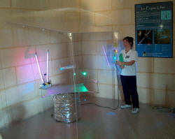 (click to enlarge)
A demonstration by the lovely Sylvia from the GDS who is practicing her
controlled flying.
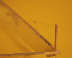 (click to enlarge)
Above shows some design modifications in response to problems developing
during the first 12 months it has been on display. Wire fracturing was a frequent
problem as the wires are vibrating for 8 hours per day. I have now used some
fine Litz wire which has 7 strands plus a strengthening fiber and is really
strong and should be much more resistant to fatigue fracture. (donated by
Bert Poole)
The other problem I have with long term lifters is HV creep and charring of
the balsa supports. I hope to deal with this with the nylon line support
shown above that gives about 1 inch extra distance of the wire to the Balsa
upright with a mild penalty in geometry as the top wire is now not
vertically above the aluminium skirt.
Lifters 4 80 kV
Nov 2005
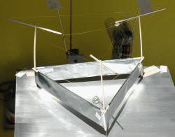
Well, here is my HV lifter running from my 80 kV voltage multiplier driven by
a flyback and ZVS driver. It sparks at about 4 1/2 inches between the wires
and skirt when turned up full.
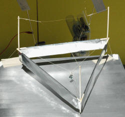
 (click to enlarge)
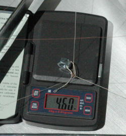
It has a LOT more lifting power and is shown here lifting 4.60 g while the
lifter weighs 4.13 g. In other words it is lifting more than it's own weight.
 (click to enlarge)
I did try dual corona wires but there was no additional benefit with this
setup. Either the extra weight penalty or load on the power supply
might have caused this result. I later removed it.
 (click to enlarge)
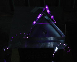
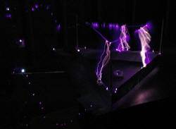
These are time exposure shots showing corona off the lifter with a few 4
1/2 inch sparks thrown in for good measure. Note the lead in wires. I have
kept the lifter on the base to avoid movement. At least the threads that
support the wires prevent arcing down the balsa supports. Left photo
exposure is 58 seconds and the right photo is 22 seconds.

