
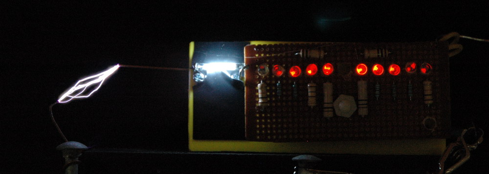
The left photo shows the spark with some red lights on the right. These indicate polarity and the LED closest to the spark indicates a negative discharge from the toroid on the left. Next the right LED lights up with the positive cycle and so on. This shows polarity for more cycles than the eye can readily see from the photo. The center photo shows detail of the LED’s. The right photo shows the same photo as the center one but with a full view also with a negative leader.
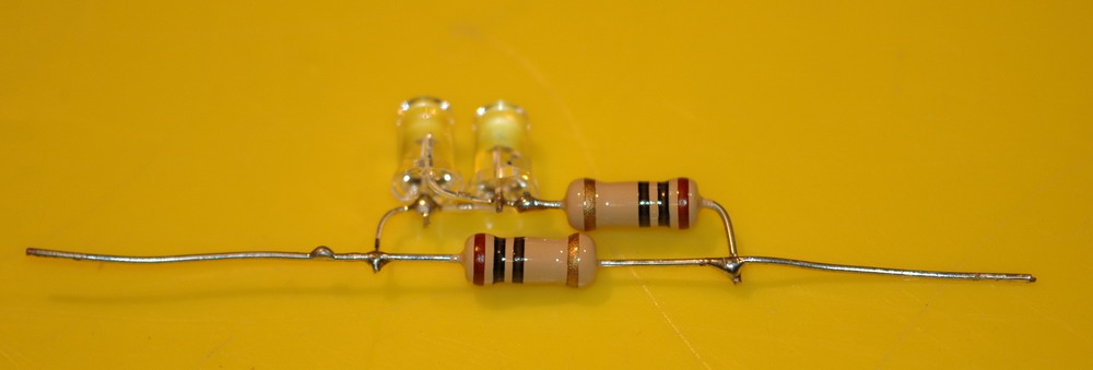
The photo above shows the red LED’s in circuit. The spark goes directly to one end and the other end is grounded. There are two 10 ohm resistors and the LED’s are connected in parallel but with opposite polarity. These values are determined by experiment and are strange but it works. For example you can’t light the LED’s with DC unless you put in 0.4 A which dissipates 4 W and burns up the resistor which has a 1 W rating. The LED’s are bright in action and since they are turned on for only a few microseconds at a time in with a low overall duty cycle, must have a very high output during this time.

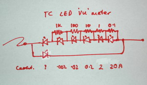
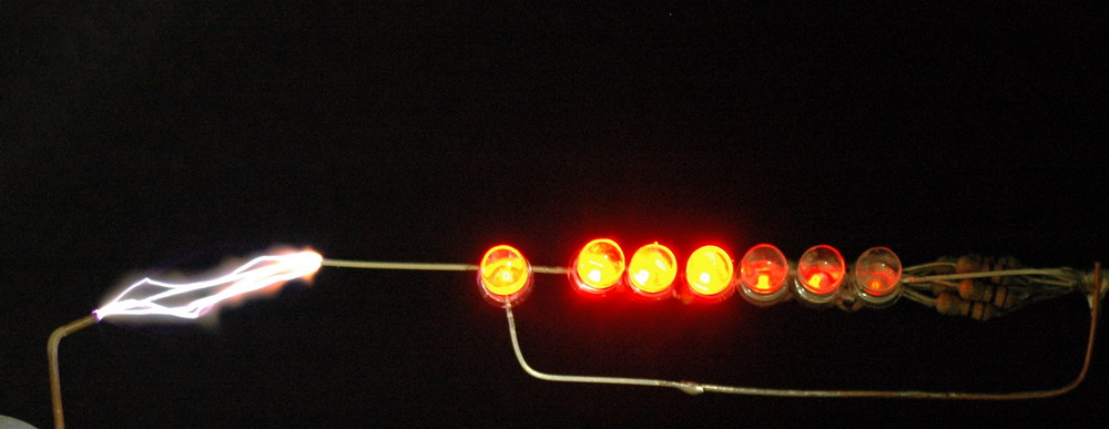
The left photo above shows a single LED being remarkably tolerant to high voltage impulses. The center photo shows the circuit diagram of the current meter and the right photo shows it in action with ignition coil sparks. The current range is a nominal .002 A to 20A and has a reverse LED as well.
All this is hard on LED’s which don’t last long. LED’s can die by degrees as below.
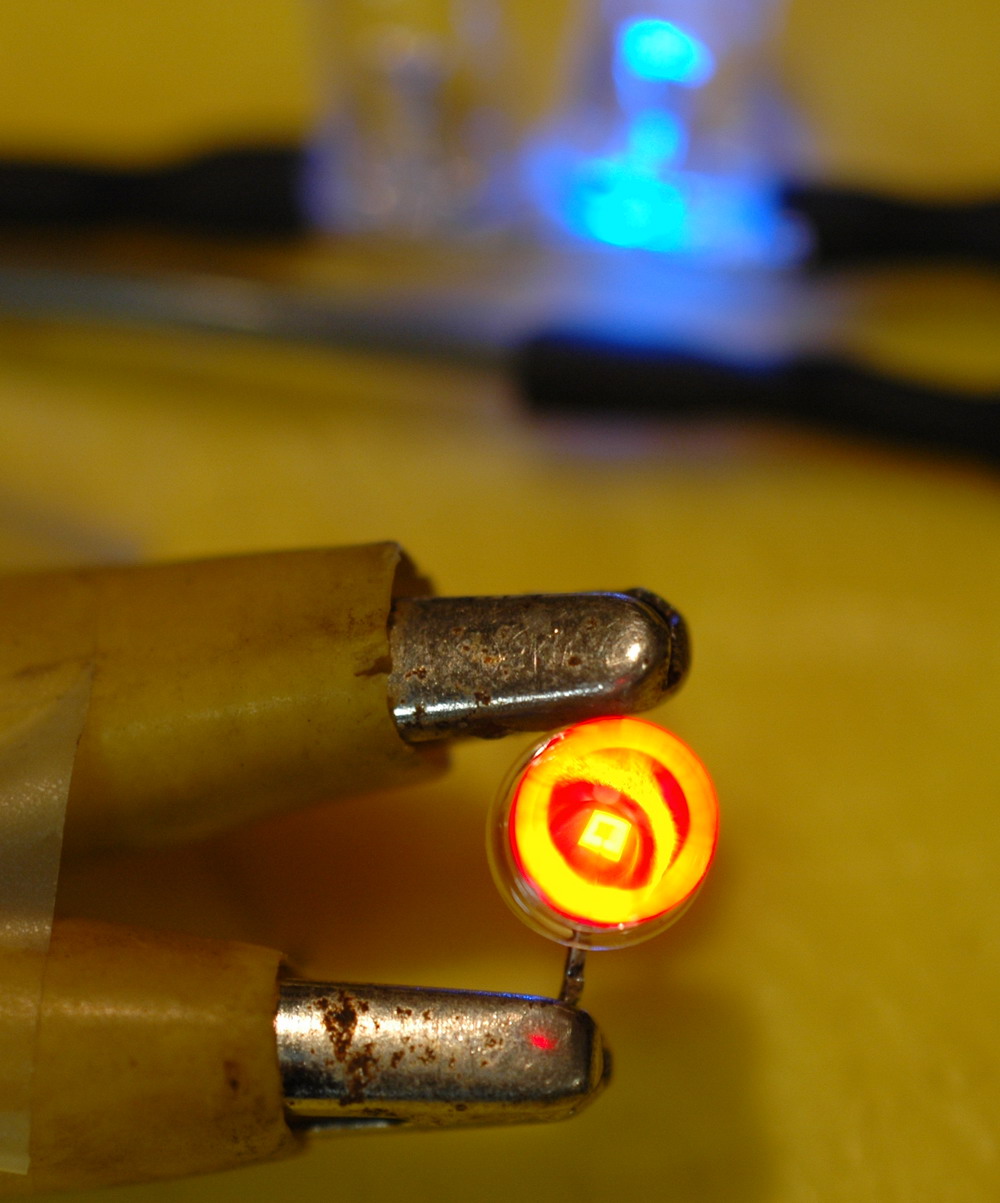
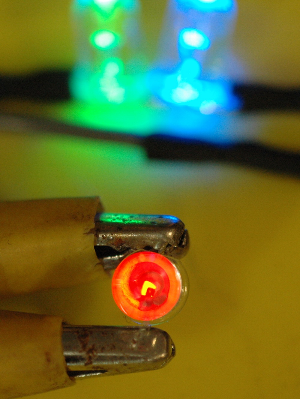

The left photo above shows a normal red LED driven by 6 VAC via a 1 k resistor plus antiparallel green and blue LEDs which is my wired test setup (very handy). Note the LED die (light emitting square in the centre of the LED. Only the blue LED lights as current only passes in one direction. The centre photo shows a partially dead LED where the square die has a non functioning area. In addition the LED is not bright and it conducts in both directions as both green and blue LED’s light up. The right photo shows a partially dead LED where the square die is still normal but the LED is not bright and it also conducts in both directions as both green and blue LED’s light up.
This is the second reincarnation of the current meter.
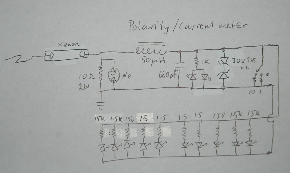
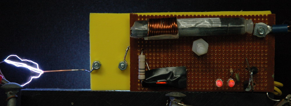
The left photo above shows the circuit diagram. Xenon light is first in series because I thought that would be most sensitive. The main current path is through a 2W 10 ohm resistor shunted by a neon. What I want to do is to remove the nastiness of the spikes then use a 1MHz low pass filter with windings on a ferrite core and a ceramic cap. After that a TVS should be able to work to limit voltages to +/- 30V and the LED’s will do the rest. The LED array should read in decades but I probably should put individual shunt resistors rather than an overall one. This needs to be redesigned as it won’t work as intended and I need to give this some more thought. The centre photo shows the xenon in action with the lights in the same horizontal line. The right photo shows the rear view with the mostly covered neon on the left and two indicator diodes on the right which should be running within ratings and shouldn’t blow but won’t be very bright either.