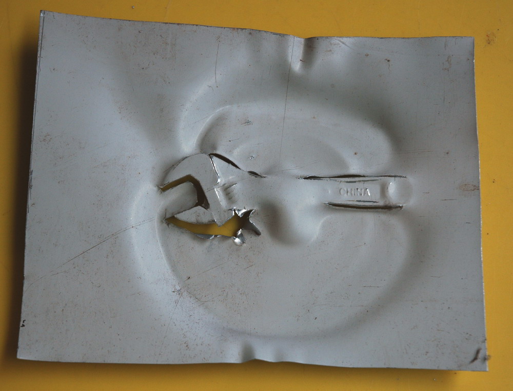
A Hall effect array is one of many different types of magnetic sensors.
“Continue reading” for interesting long exposures and construction. 5 photos and links….
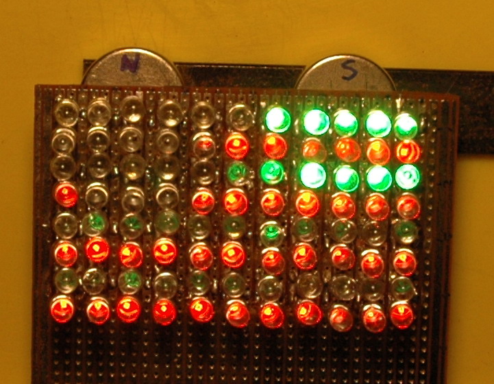
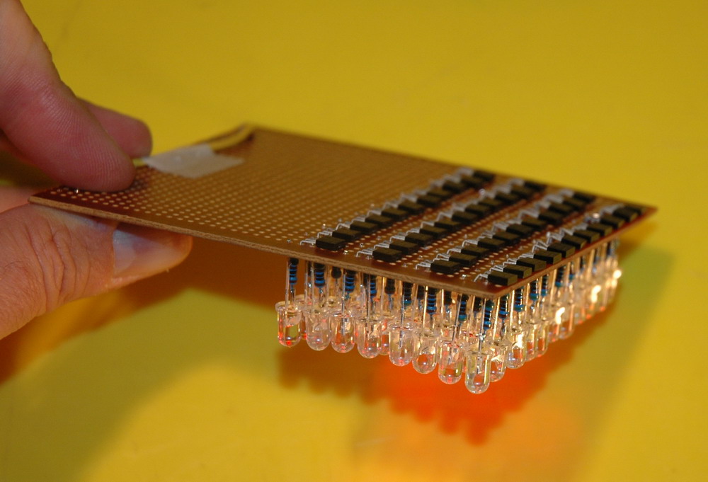
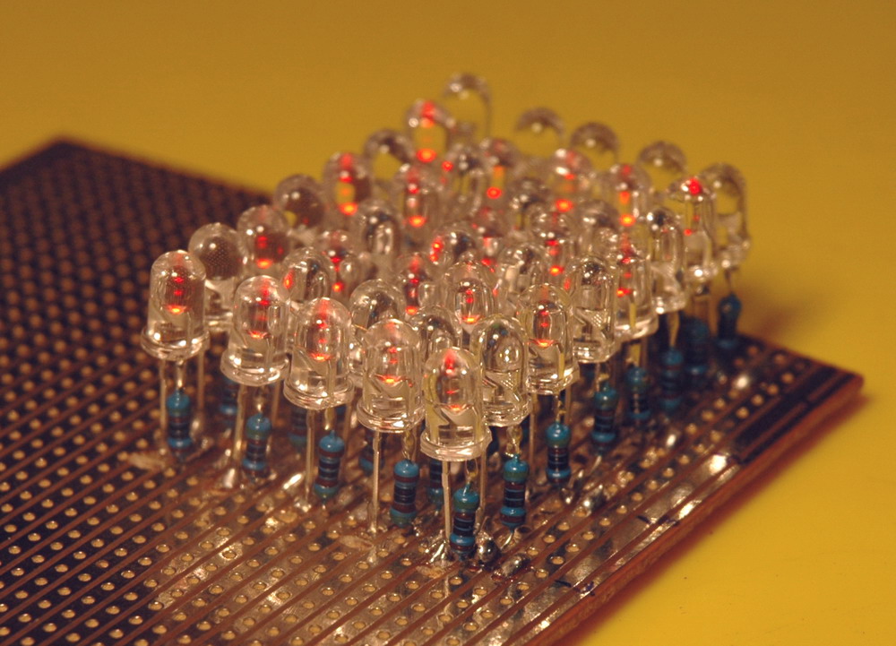
For the Hall effect array I have used 2 LEDs and two resistors as the simplest circuit I could arrange to show North, South and no field. This gives a visual indication of a magnetic field and its direction. It contains 44 UGN3503 Hall effect devices as the magnetic sensors. They output 2.5 V in no field. Present a south pole and voltage goes up by by 1.3 mV/gauss and the same in the reverse. (10,000 gauss = 1 Tesla). They run on 5 V and the 44 device array shown here draws 500 mA.
There is room on board for 88 Hall effect devices if I wish to expand. Note that this array gives a real time response with a frequency response of 23 kHz which is in the range of my can crusher. It responds to the slightest movement with intensity or colour changes and is a lot more dynamic than the still photos would indicate. Think of a colour Magnadoodle R. The circuit uses the output which sources current at a sufficient level to drive the red and green LED’s which connect to ground with their respective 510 ohm resistors. The differing response is due to the different voltage drops with red LED’s being in the 2 volt range and green LED’s in the 3 volt range.
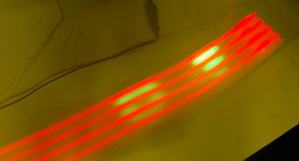
A small array of only 4 magnetic sensors can give a picture of the underlying magnets on a longer photographic exposure of only a single pass.
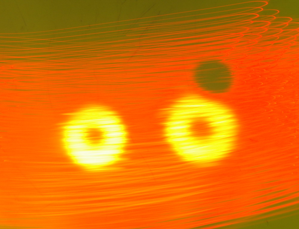
Magnetic sensors array showing the south poles of two toroidal magnets and one North pole of a NIB magnet
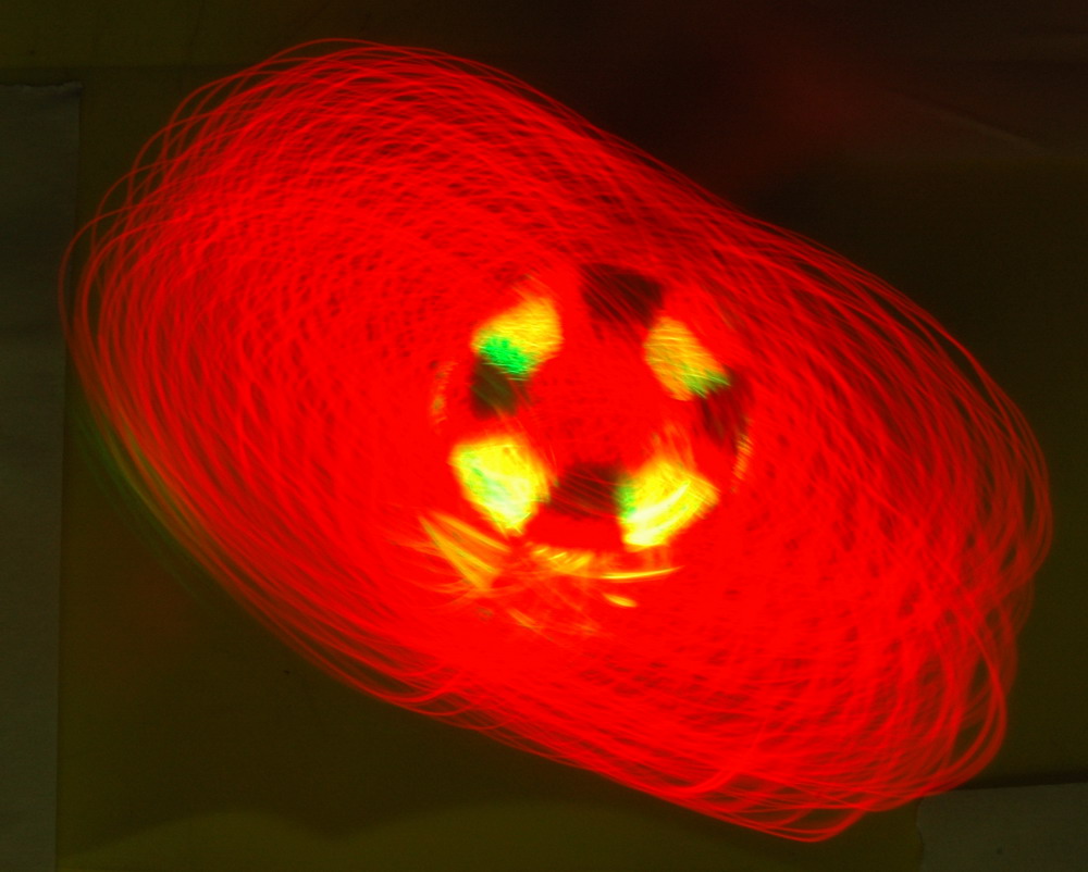
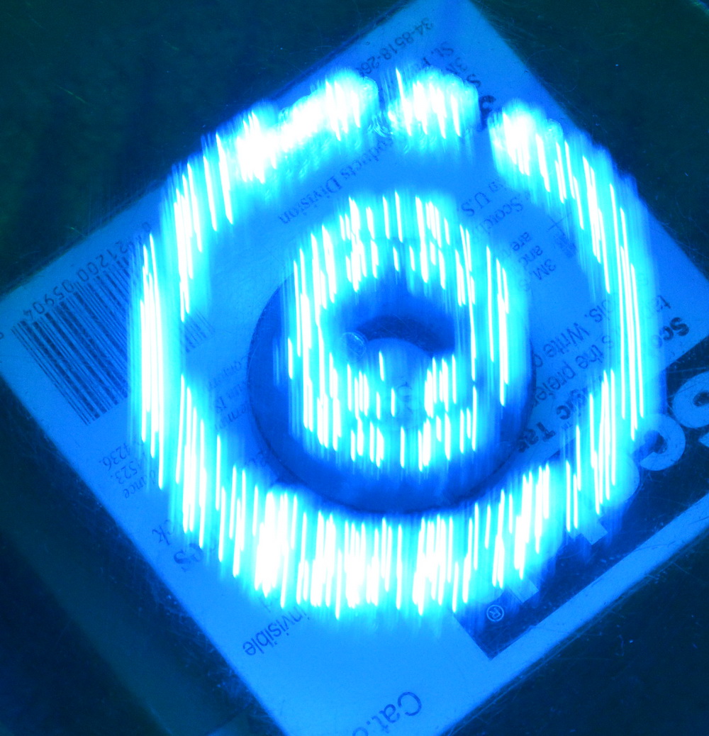
More magnetic sensors and more movement can map more complex fields. Black is south and “yellow” (=red plus green LEDs) is North. Above, left shows the array moving by hand in a time exposure shot of 4 seconds with magnets below the plastic sheet. It has many passes over 3 magnets. There are two south poles of two ferrite rings and a stronger NIB magnet adjacent showing a (black?) “hole” where the NIB has been turned north up. Hand is faster than the eye here. The right photo shows a more complex multi sectored magnet out of a video motor. Note that the fields do not line up properly as the red and green LED’s are physically separated by 5 mm or so.
One of the advantages of this type of array is that each element will have a speed limited by the sensor which is a nominal 23 kHz. There will be no obvious delay if the array is passed quickly or slowly across the magnetic field. On the other hand, if a computer was to scan each of 44 elements then it would need to be able to process a rate of 23 x 44 kHz = 1.012 MHz. A small processor at 8 MHz with 10 clock cycles per scan would only just cope.
Related pages
Try something else
External links
Hall effect sensors – Wikipedia
Photo Date: June 3, 2006
