 Can Crusher 4 using a pulse capacitor bank rated up to 10 kJ. Time to get serious! My big caps have arrived. Total stored energy with all charged to capacity is 10 + 10 + 8 = 28 kJ.
“Continue reading” for more details and photos.
Unfortunately, the voltage ratings are different so they can only be charged to the 12 kV if in parallel but still 16 kJ can be achieved as a single unit. 
 Features 215 uF (112 + 51.2 + 51.7), 12 kV max (16 kJ) The caps are all in parallel which limits the voltage rating to the lowest cap ie 12 kV. Minimal conductor length. Total path is 21, 25 and 30 inches for each cap to terminals and back. Inductance is of the setup is 200 nH with a 6 inch straight wire across the output terminals. The individual caps are 80 + 40 + 40 nH in parallel. Resonant frequency is 25 khz (period 45 us) for the 215 uF. it is measured by looking at the ring frequency on the CRO with a small energy discharge into the wire short circuit. Heavy copper bus bars. Mostly 1 1/2 inch by 1/4 inch. Switch is mechanical activated by pulling out a plastic spacer with a string (simple solid and reliable).
  Spring force is from two bedsprings. Copper braid (2 inch) connects to a copper plate as one contact (I will replace with brass later). Switch contact on coil side is a hinged 1 inch brass rod with a neoprene pad under it as a damper. Contact is solid and does not seem to bounce. The angles will result in a bit of slide on contact. Large wood blocks absorb any force and are braced with the welded can edge rather than the insulator or HV terminal. Terminals are brass but main bolts to case and HV terminal are steel. Voltage measurement is via an analogue meter and 20 Mohm chain. Lights. Flashing neons x 4 with increasing rate with increasing voltage from 250 V to 12 kV. Also single neon that lights with cap voltage down to neon threshhold of 70 V. Discharging is via two 30 k ?50 W resistors. (has to be intermittent due to inadequate rating) Charging through same 30 k x 2 resistors through my MOT supply at present until I get the NST supply running.
 The left photo shows the light blue Maxwell capacitor specs. 110 uF, 12 kV, 8 kJ, 75 kg. General Atomics have given the specs as 80 % rated voltage reversal at 100 kA. 75 A RMS CW current. Design life 30,000 shots or 1600 h DC. Inductance 40 nH. The right photo shows the 2 gray Aerovox capacitor specs. 50 uF, 20 kV, 10 kJ each. They are smaller and despite the higher energy are rated at only 20 % reversal. They were apparently used for ‘Star Wars’ laser work and saw only 2 hours service in the 1980’s. These are all proper energy discharge capacitors with low inductance low profile, high current terminals. They are all second hand so remaining life is not known. I built the special trolley for it to accommodate various experiments as 195 kg is just too much for me to lump around. The total energy able to be stored of 28 kJ can be compared with the kinetic energy of an AK-47 bullet of 2 kJ in flight. An exceptional level of care is required to avoid unintentional discharge in close proximity in view of the extreme sound / flash / EMP levels. Also metal fragments of exploding coils are of high velocity and very capable of injury. With these I hope to be able to do a variety of interesting things such as extreme can crushing, coin shrinking, exploding wires, and projectiles as well as a couple of interesting pulsed Tesla coil experiments.
 Left photo shows a 1 kJ shot at dusk to get the exposure long enough so I could coordinate a pull on the string and take the shot. The right photo shows the gap wear is fairly mild but I have only had a few shots at 4 kJ max at this stage. Still so sign of failure or problems so should handle higher powers yet. Peak current was 70 kA so far. Actually there is surprisingly little black copper oxide charring. I attribute this to the hard positive contact with little bounce. Note the nick in the braid from an exploding coil (or the aluminium tube as it disappeared down the wormhole portal). I am still using the same switch and contacts 2 years later in October 2007 so it has been durable and reliable.

 Left photo shows the a can crushed and torn apart at 4 kJ. The right photo shows the coil distortion from a similar power shot. Since the peak can current is around 2 times that of the coil current (see below), then a 70 kA coil current suggests a peak can current of 140 kA.
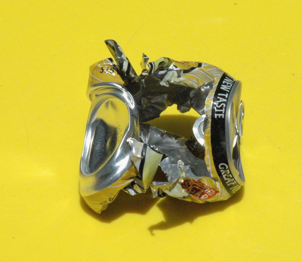
 Left photo shows a frozen can fired at 2 kJ. Note the folding and wrinkling and apparent area of missing can. The centre and right photos show similar shots.
 Left photo shows a can in a longitudinal coil about to be fired at 4 kJ. The right photo shows the result. What will happen here with a split can (1/2 inch gap) and 1 kJ shot?
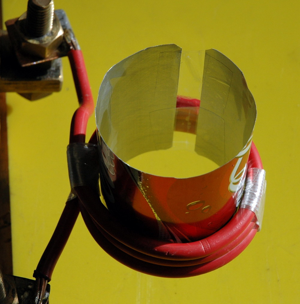
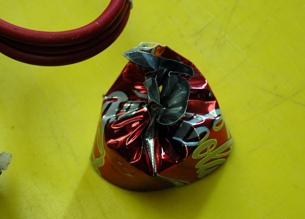
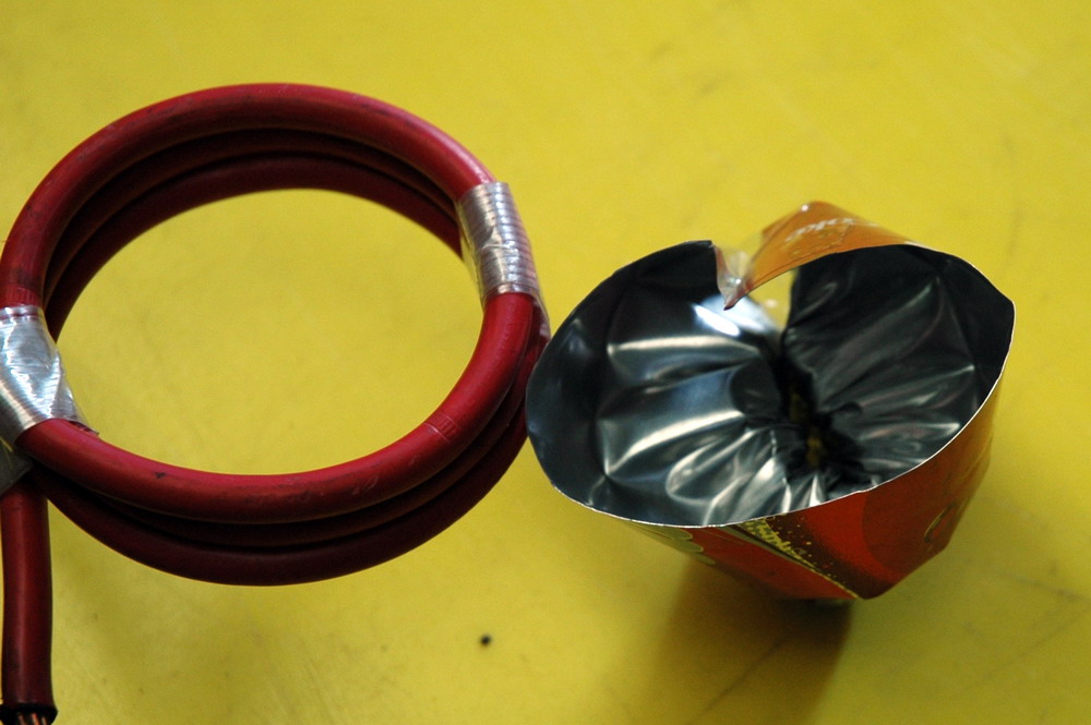 Left photo shows a can with a split about to be fired at 1 kJ. One might expect that eddy currents won’t appear and that nothing will happen. However, the centre and right photos shows the result almost indistinguishable from a 1 kJ shot with a complete can with top and underside views. Why? Because there is still a large return path for the eddy currents where the field is lower around the top and bottom rim of the can.
 Left photo shows an interrupted strip about to be fired at 1 kJ. The right photo shows the result. There is no crushing In this split can strip. It is more narrow than the windings, hence the field is uniform and there is no return path for eddy currents. This is despite the similarity to the interrupted can above. Hence here it really does matter that the strip is broken.
 Left photo shows a flat sheet about to be fired at 1 kJ. The right photo shows the result which is minimal distortion as the eddy currents would be formed at right angles to the sheet.
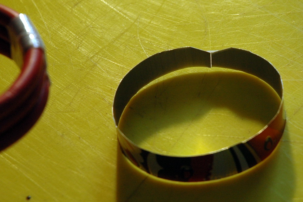
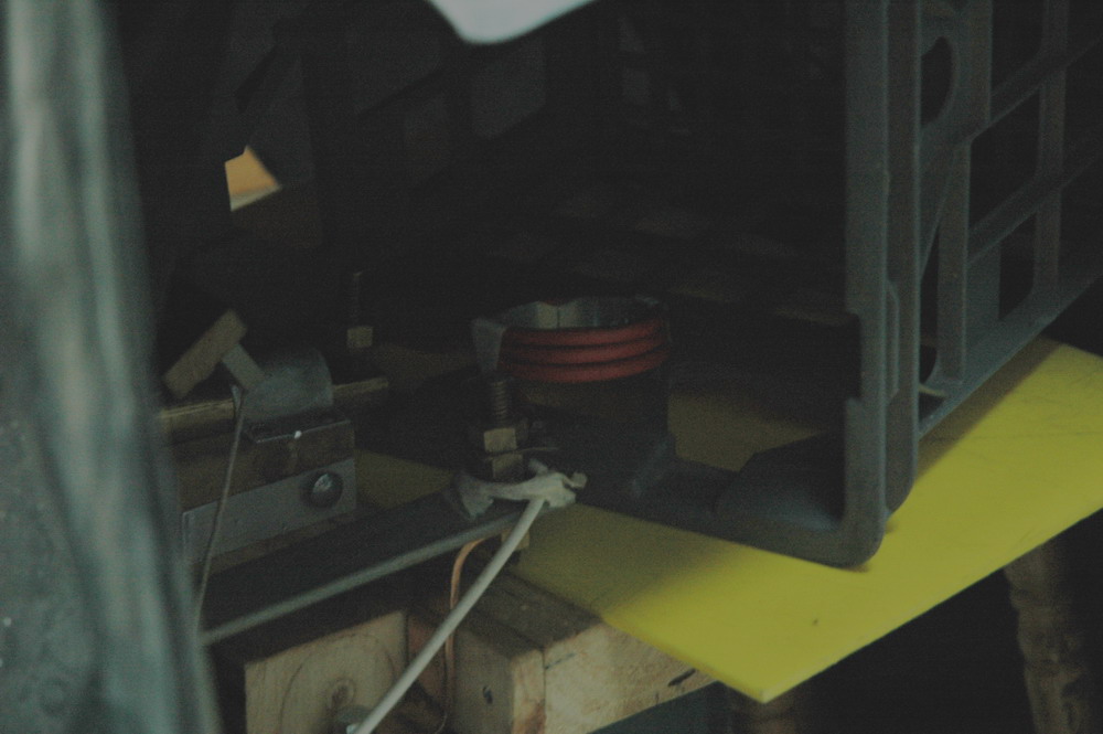
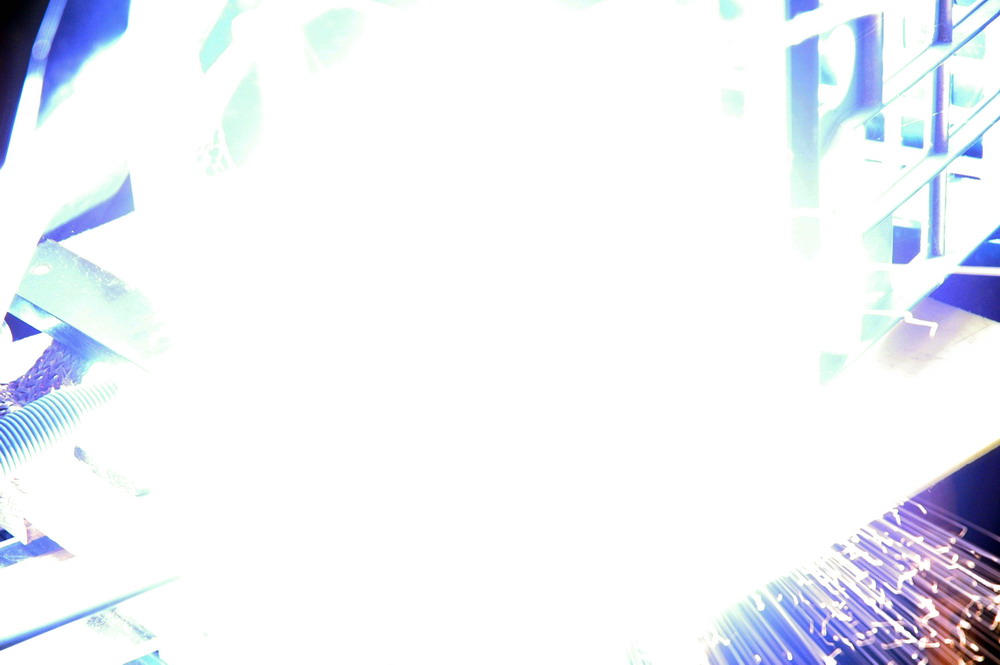 Left photo shows a can strip with a fine split about to be fired at 1 kJ. The centre photo shows the setup before firing. The right photo shows the flash of both the main contact as well as arcing across the gap in the strip. Note the shower of sparks from the strip arcing in the bottom right. You can tell this by ray-tracing back to the source.
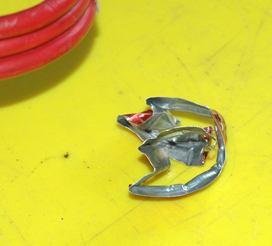
 Left photo shows the crushed strip from the shot above at 1 kJ. Remember that this won’t crush if there was no connection so proof that it did arc across . The right photo shows the strip reformed into a circle to show the vaporized ends.
 The left photo above shows a double winding of 3 + 3 turns in the same direction about to be fired at 4 kJ. The centre photo shows the can which has been split in three. The right photo shows the remains of the coil which is broken is several places.
Now the CRO shot (20 kA/div and 50 us/div) above is interesting. The current curve on the CRO shows the current ring down from a peak 45 kA with 65 % reversal, broadly as expected. Just after the peak (about T + 40 us)there is a spike of current then the curve looks funny after that and the period of the first voltage reversal reduces to about 35 us. The next is 55 us and the last around 55 us as well. So how to explain that. The reduced period suggests that the inductance is reduced. However the exploding coil will try to increase its inductance by expanding radially and contracting longitudinally. The likely explanation is that there is shorting of the turns occurring. Perhaps the current spike is when this occurs. But then the period returning to normal needs to be explained. Perhaps the expanding coils no longer contact after the first reversal. So when did the coil disrupt and break? I am not sure and I suspect that it may not matter as much as one might think (controversial statement). Try interrupting 40kA flowing through a coil at 6 kV and see how long an arc can be drawn. There is certainly evidence of major arcing with burn marks on the plastic and wire. The spark may well have continued even with coil disruption of many inches. This of course has implications for Bert Hickmans statement that coin shrinking with exploding coils is gentler on the cap because it avoids the voltage reversal (in comparison to can crushing where the coil remains intact). I will try the effect of fine wire to see if this supports an arc hypothesis maintaining the integrity of the coil even when it no longer exists. Below is an experiment to test whether fine wire (.024 inch) will maintain crushing at 4 kJ due to the arc despite the wire being vaporised. This is in comparison to the heavy wire before in which the can was divided into three parts. To keep the physical integrity of the coil with a comparable mechanical strength to the heavy wire, I have put it in thin plastic tubing. Of course the mechanical strength is actually very different between the two and this does limit the experiment. 
 The left photo above shows the setup with the heavy lead in wire joining to the thin wire in the plastic tubing. The centre photo shows the coil mounted on the can. Note that the coil is actually thin wire inside a plastic tube. The right photo shows a can after 4 kJ with minimal crushing and the coil has been vaporised. No copper remains in the tubing which has been split along its length and blackened from the copper oxide. There was no remaining charge in the capacitor.
 The CRO readout above of current on the same scale as before (20 kA/div vertical and 50 us horizontal). This shows a small current pulse of perhaps 9 kA with no reversal. Fine, but after almost 200 us there is another pulse of almost 30 kA with no reversal. Explaining this second contact is more difficult. Switch bounce is possible in retrospect but I will have to check how the safety box was positioned as this shifted as one of the panels separated and my have interfered with the switch. Alternatively, the wires may have recontacted but this seems unlikely. I may need to repeat the test when I get more tubing. Here is a well spaced spiral wind of a can that is full and FROZEN. Unfortunately I missed the current reading on the CRO but it was out of range and over 80 kA. Looks like I will have to reset my Rogowski for 200 kA FSD. Unfortunately, I only finger tightened the bolts so there was some charring around the contacts and a bit of destruction of the brass thread.
  The left photo above shows the setup with the heavy rectangular 3 turns. The right photo shows the can after with a rough spiral cut. The work coil wasn’t even dented and the can was not disrupted. I was still able to slide it out of the plastic covering which was not punctured. Lots of small aluminium particles. Basically, it had nowhere to go. The shot was “relatively” quiet as well. I probably lost some energy with the loose bolts though. 5 kJ is my biggest shot yet. I suspect it would have been over 100 kA though. Beyond the limit of the Maxwell alone but not the three caps together. No problems so I can push the can crusher higher.
 The left photo above shows a 3 kJ can crush. The right photo shows a few moments later. It was gettting a bit dark by the time I got set up. Listen to the can half hitting the ground a few secs later. Also showed an area of poor contact and sparking which I will have to investigate. You can just see the coil itself being launched. I don’t initially understand why so much current could be passed between the cap cases as all my bus bars look secure. The simple explanation for the arcing between the caps is the inductance of the busbars. Even though the resistance is low, the inductance will be significant which is why they need to be as short as possible and as large as possible. Consider the inductance of 20 cm of busbar compared with 60 cm wire in 3 turns of a can crushing coil (?300 nH). Without calculating it I would guess at the busbar being 10 % of the inductance of the coil. So at 6 kV across the coil this would be 600 V at perhaps 80 kA peak current. Short that out and you will have plenty of sparks. However, a slow DC constant discharge will not be affected by inductance and the DC resistance may be very low. I should try some measurements on this. Related pages External links Try something else Photo Date: Oct 2005
Related pages
Try something else
External links
Photo Date: