 Coin shrinking a Japanese coin to half its diameter while preserving details. Bonsai for coins. You can still see the Japanese characters miniaturized on this one yen coin. “Continue reading” for the details of the huge currents involved to make small change.
My previous attempts at can crushing were limited to only 1.5kJ and were not really successful but helped to understand the process.
The work coil is disintegrated with higher powers. To delay this I have used a fibreglass interturn spacing and have immersed the whole thing in a block of ice.
Normal coinshrinkers use a coil and some dowel but no external support. I wanted more of the force to be directed to the coin and to keep the work coil in proximity longerbeing light and aluminium.
 Fibreglass reinforces the windings and it is all placed in a 4 inch PVC reinforced ice block.
The work coil is 10 turns of 2mm wire. The key is that it was interwoven with fiberglass cloth as the axial forces will slam the coil turns together and short them out. Plastic would get squashed but I was hoping the fiberglass might do better. The whole thing was then wrapped in cloth from some garish print dress (not mine). It was then placed in the 4 inch PVC end cap and short pipe, filled with water and frozen. That in turn went in another layer of end cap and pipe with the gap filled with water and frozen. The hope was that the cloth would add strength to the ice like glass fiber does to epoxy to give fiberglass. It was all enclosed in a wooden box. I hid behind a blast shield and also had the setup monitoring current on the CRO with a Rogowski coil. So here are the setup photos and the damage done following a 5 kJ discharge.
 The left photo shows the ice was shattered as were all the PVC components and a panel was broken off the box. It wasn’t that loud using hearing protection and much less than an exploding wire. The right photo shows the wire fragments. Interesting how one part of the coil is almost unscathed apart from doubling its diameter where the other half is fractured, compressed and in pieces.
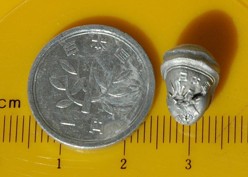
 The left photo shows the coin shrunk to 50% of the former diameter of 20 mm. It is now 10 mm x 14 mm. The coin was a little unsupported on one side so I expected a bit of a lopsided result. It is interesting trying to see the corresponding detail of the Japanese characters. The right photo shows the numeral 1 which looks like it is fracturing out.
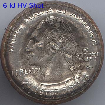
 The left photo shows the current reading from the Rogowski coil which indicates a heavily damped waveform with a peak of ‘only’ about 50 kA. (50 kA/div, 50 us/div) I had expected more. There are no discontinuities to fit with the wire disintegrating. The right photo of a test run at only a few joules prior to the main shot (?2 A/div, 50 us) shows the waveform of the same combo but with much more prolonged ringing. It would seem that at full power the energy is being dissipated much faster although it difficult to be sure since the amplitude on screen is so much different. These guys from Hackerbot labs have a 100,000 frames per sec video of a 15 kJ coinshrinking shot. A word from Bert Hickman who is the guru for this stuff. “Unfortunately, electrolytic caps probably won’t work very well. Making an efficient coin shrinker is similar to making an efficient Tesla Coil – its a balancing act. For a variety of technical reasons, the “sweet spot” for coin shrinkers falls in the range of 2.5 – 10 kJ of bank energy, 5 – 20 kV of initial bank voltage, and 20 – 300 uF of bank capacitance. Because of the huge forces involved in coin shrinking, it is impossible to keep the work coil from being destroyed. The best you can do is delay its destruction until AFTER the coin has been shrunk by taking advantage of the inertia of the winding and robustness of the insulation system. We’ve found (experimentally) that we get best results using a single-layer 10-turn close-wound coil made using 200C double-build polyamide-imide magnet wire. Such a coil will “survive” (although significantly changing shape) for about 50 – 70 microseconds when subjected to the 30 – 60 kA sinusoidal current peak required for coin shrinking. It gets squeezed axially, and stretched radially until the copper is pulled apart and adjacent turns short out. Maximum shrinking force occurs at the first current peak and is a function of the square of the peak current. So, the first 1/4 cycle current peak should occur in less than 50-70 microseconds (from above). I’d suggest aiming for 25 – 60 microseconds in a new design. This limits the period of oscillation for the work coil and bank capacitance to about 100 – 240 microseconds, corresponding to a minimum natural frequency in the range of about 4 – 10 kHz. For typical “coin size” work coils, the coil inductance is in the range of 1.4 – 3.5 uH. Wiring, switch, and capacitor bank inductance may add another 1 – 2 uH, which limits the “sweet region” for bank capacitance to the 20-300 uF range mentioned above. For a given bank energy, using a smaller capacitance at higher bank voltages may cause premature flashover/failure of the work coil, often long before the first current peak is reached. An interesting side-effect is that the perimeter of the coin often becomes markedly thicker than the interior (“torroided”). Following is a torroided quarter shrunk by Texas shrinkers Bill Emery and Phil Rembold using a higher voltage bank: http://www.capturedlightning.com/frames/gallery/hv1b.jpg Using larger bank capacitance at lower voltages may permit the work coil to self-destruct from magnetic forces long before the first current peak is reached. Again, the coin stops shrinking prematurely and remaining bank energy instead goes into the coil explosion and plasma.” See the discussion of my coinshrinking on the 4HV forum.
Photo Date: 2005