I have upgraded the Tesla coil at Scitech. This is a non profit organization whose mission is to increase interest and participation by Western Australians in science and modern technology. It has been open since 1988 and has 250,000 visitors annually.
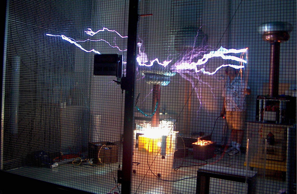
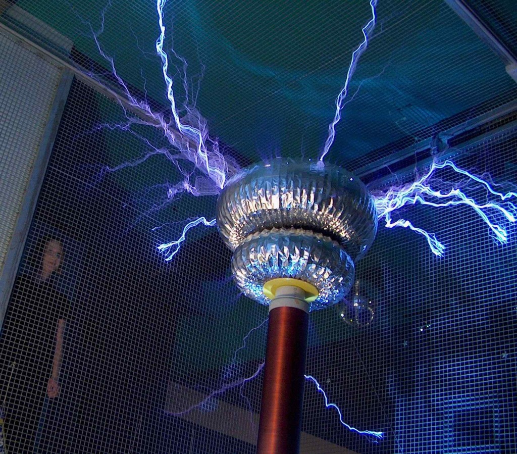
On the wrong side of the Faraday cage (above), doing the demo in Feb 2003. An earthed PVC rod with steel wool on the end gives a sparkler effect if the sparks are hot enough. To the right in the photo is Scitech’s TC which needs some work.
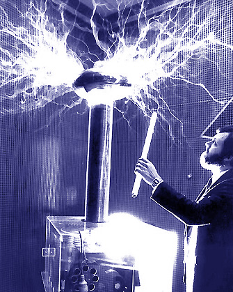
My interest and involvement was sparked (pun intended) by its Tesla coil which was made by Stan Deyo in around 1988. It has functioned reliably with little modification since. The black and white double exposure publicity shot at the time is shown below on the left.
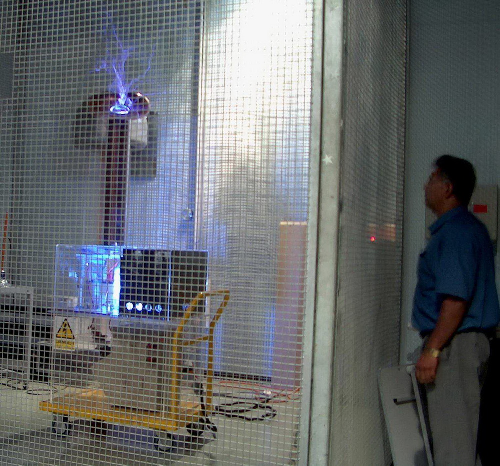
I was able to see the Tesla coil in Feb 2003 with my son, Michael. He expressed disappointment at how short the sparks were, having only seen my Tesla coil at home. It was reeally not performing well with perhaps 2 foot streamers despite using a 5 kVA pole transformer. Truly, here was a noble cause worthy of assistance.
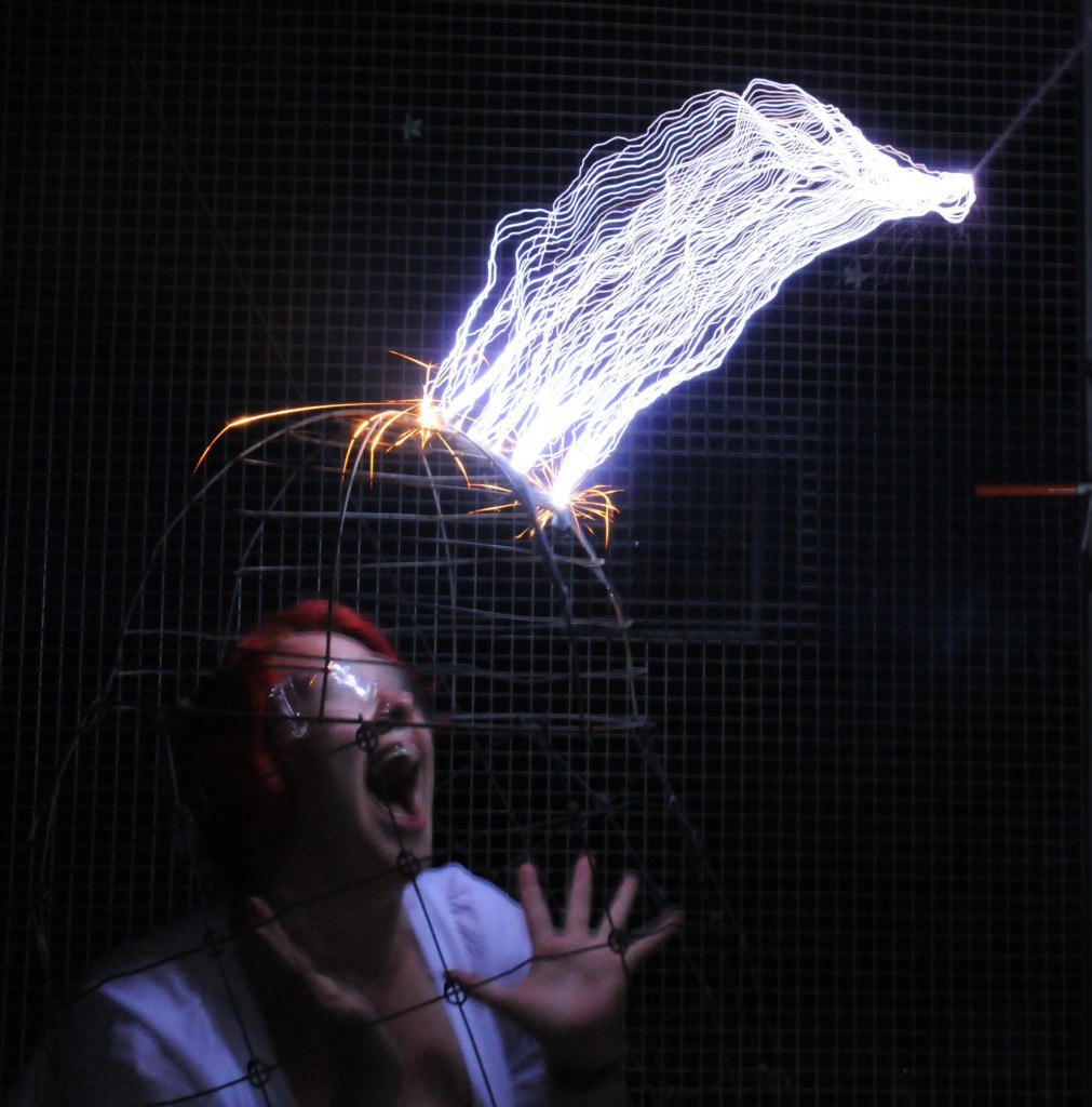
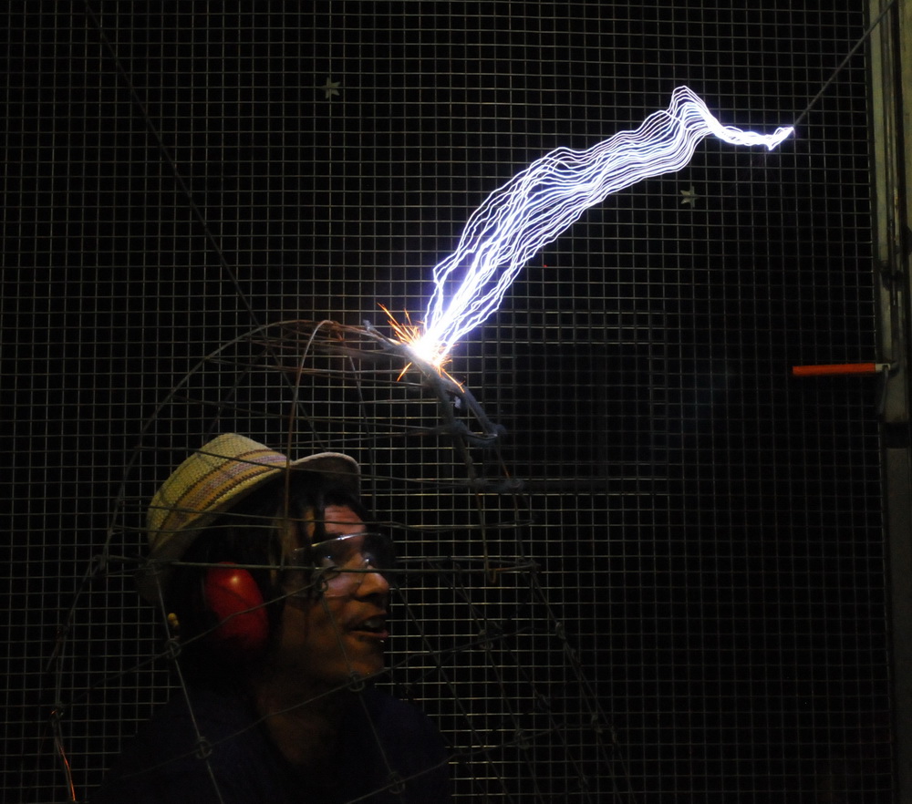
The best picture I could get showing only small streamers (above right). Despite retuning, doubling the topload, and doubling the capacitance only about 3 foot sparks could be obtained. The staff were keen to upgrade and I gave a demo of my 4 inch coil and micro wave oven transformer supply, which gave sparks up to 4 1/2 feet above (top photo).
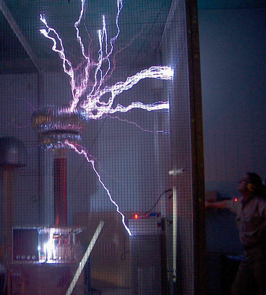
This is the upgraded Tesla coil installed 2003.
In June 2003, my 6 inch coil was installed with a significant improvement in performance (above). The sparks are now a lot hotter and are out to around 4 feet. The length can be estimated by the 36 inch length of the secondary to the base of the toroid. Still less than hoped for but a much noisier and more impressive display.
Schitech demonstrators, Renae and Chris in my Faraday cage inside their cage at Scitech in 2011. This was for a radio promotion that was planned but didn’t get off the ground due to public liability issues. A custom cage was planned but didn’t eventuate despite everyone’s enthusiasm.
Technical specifications (original) 2003
The original Scitech TC components included a 5 KVA pole transformer 250 V to 12.5 KV with a soft start and extensive mains filtering and monitoring. It is ballasted with 3 paralleled heater elements which glow red hot after a minute or so of continuous operation. It has fuse limiting to 16 A.
The motor is an ARSG running on DC 180 V with 8 tungsten 1/2 inch rotating electrodes and 2 stationary.
The 2 tank capacitors are each 20 nF mylar (total 40 nF at 20 kV).
The previous primary was around 2-3 turns and the secondary is 6 x 30 inch with around 420 turns.
The topload was a 5 x 12 inch gold plated copper toroid.
The construction of this coil and the Faraday cage was of very high quality and the long service a testament to this.
Technical Specifications (upgraded) 2003
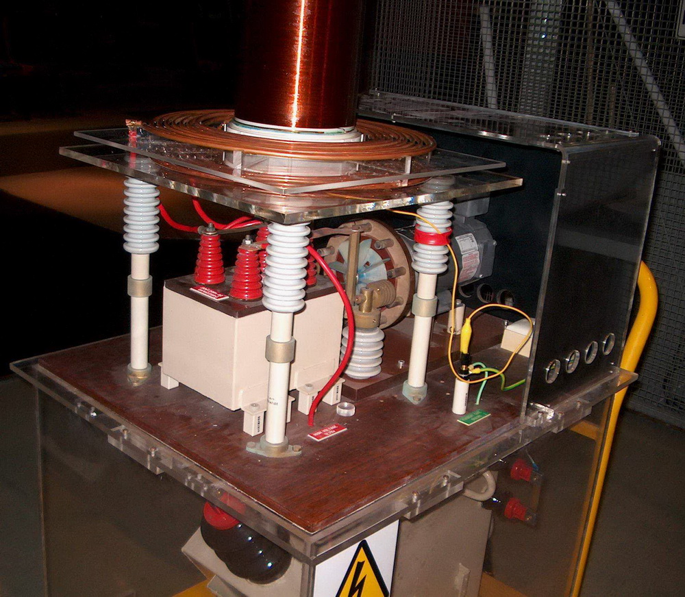
The coil during modifications (above) with the new double layer primary and new secondary. The double layer was needed to accommodate the larger number of primary turns (8 above, 5 below) in the same physical space as the previous 3 turn coil.
My changes were to:
1 Replace the secondary with 6 x 32 inches with 1280 turns (previously 6 x 30 with 400 turns).
2 Replace the primary now tapped at 8 of the 13 turns.
3 Use a larger topload of a 12 x 29 inch toroid with a smaller 8 x 20 toroid beneath it.
4 Add my Cornell Dubilier MMC capacitor of 45 nF to the existing capacitor (total 89 nF).
5 Run the motor from 200 V DC (previously 180 V).
6 Fit low profile strike rails.
7 Use an inductive ballast (below) instead of the resistive one.
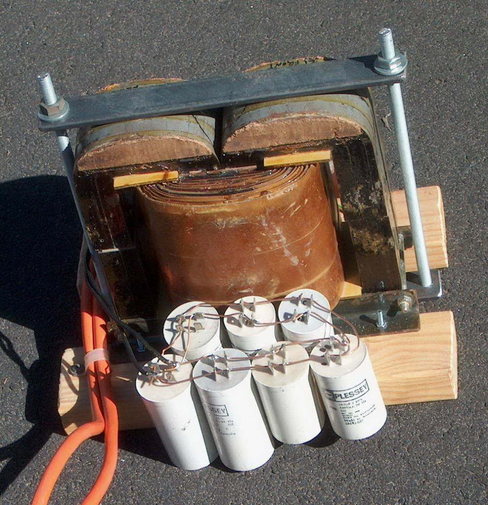
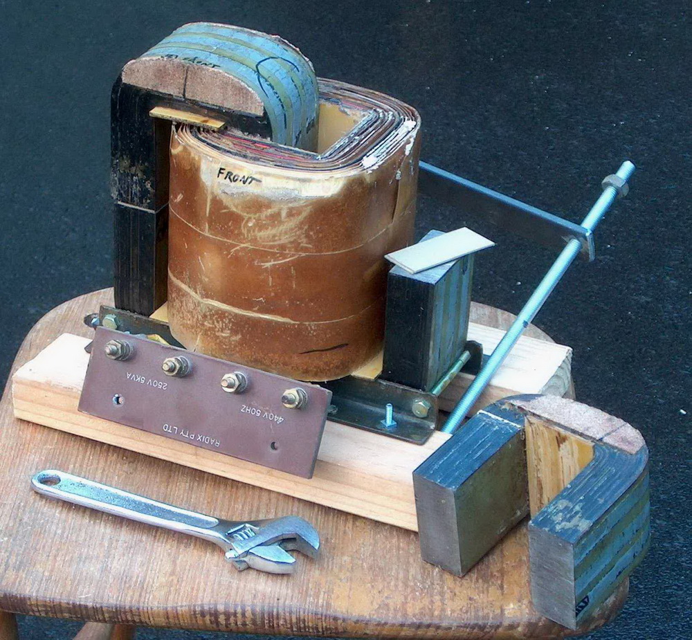
It weighs 30 kg and has a core iron cross section area of 47 cm2 (= 7.3 in2). The inductive ballast (above) made from a modified 440 V to 240 V transformer rated at 5 KVA bought at a junk yard. The four ‘C’ cores were taken apart with gentle persuasion from a large hammer, and an ‘air gap’ made by using a cardboard or acrylic spacer between the cores. By using 0 to 6 mm spacers the current draw on the 240 V winding can be adjusted from 1 A to 30 A. This corresponds to an inductance of 1.0 down to 0.04 Henries.
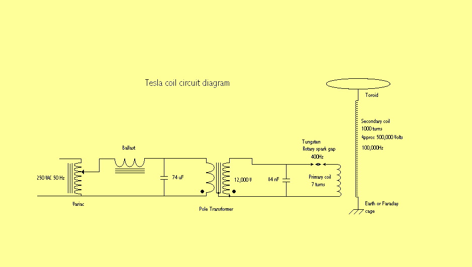
The resonant charging capacitors (also shown above) of 74 uF is the sum of the 7 polypropylene capacitors that I had. It is in series with the ballast and in parallel with the pole transformer. Using these capacitors results in a higher voltage across the pole transformer input. Testing with a 10 KVA transformer as a load with a 240 V supply resulted in 280 V across the transformer with the capacitors compared with 195 V without. In other words this arrangement gives a higher voltage than the supply and will limit total current draw which generally sounds like a good thing. In practice, however, it did not improved the performance or current draw and has been left out.
Related pages
External links
Try something else
Photo Date: 2003 – 2008
