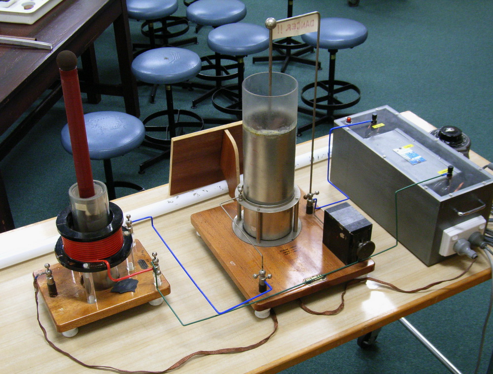
 The Physics Dept of the Uni of Western Australia had this Tesla coil which dates back 40 years. Made in Germany according to the nameplate. Apparently runs at 1 MHz but lots of problems with the Leyden jar caps. It still not functioning despite various attempts so despite the historical interest it was felt a new one was needed of more modern design. So I put my hand up.
For more details and photos:
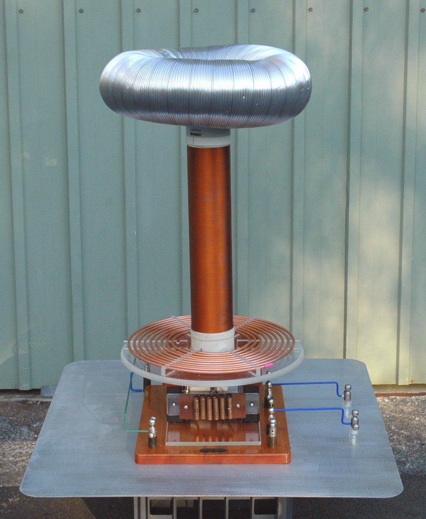
Accordingly I made up this 4 inch diameter Tesla coil. I tried to incorporate the historical aspects of their 40 year old coil such as both the wooden bases with original manufacturers plate and the antique terminals and some of the solid wiring in a hybrid acrylic/antique setup.
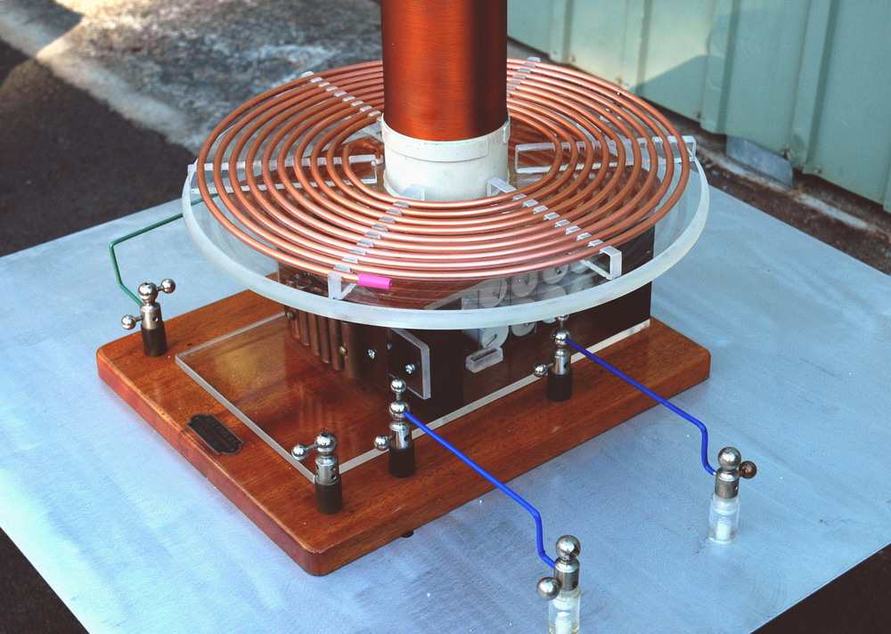 The coil is conventional and was intended to be powered by one or two 12 kV 30 mA NST’s but they found an 11 kV 110 mA NST in storage. Secondary is only 840 turns. Caps are the “standard” Cornell-Dubilier CDE942C20P15K-F 0.15 uF, 2000 VDC in two strings of 15 ie 20 nF and the gap is a static 5 gap copper tube array.
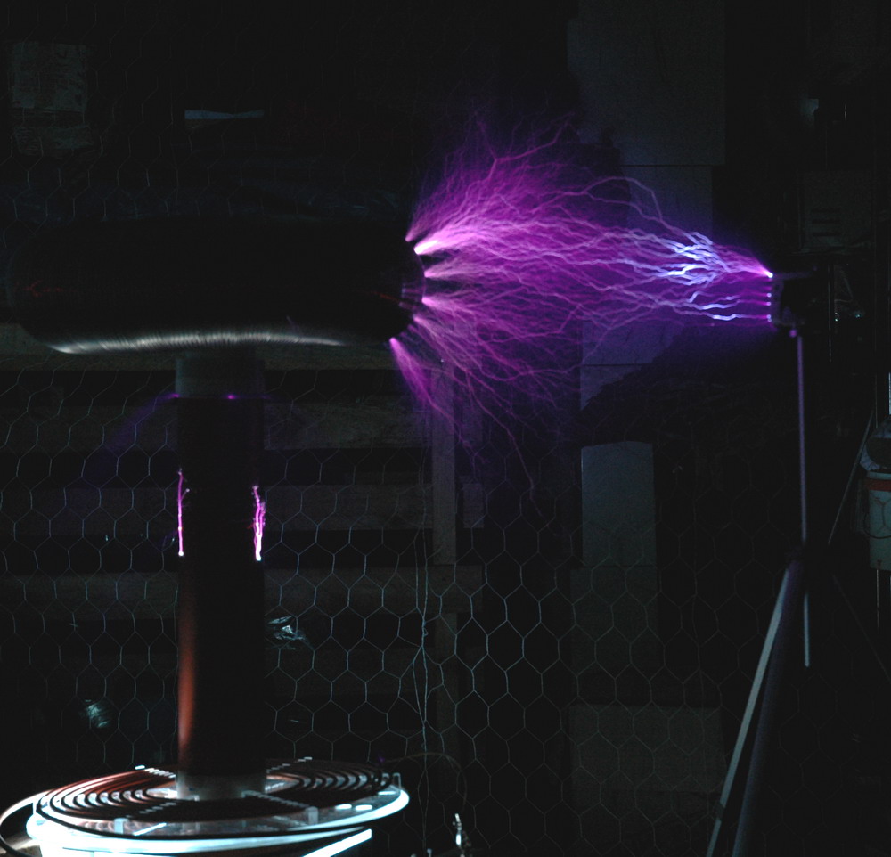
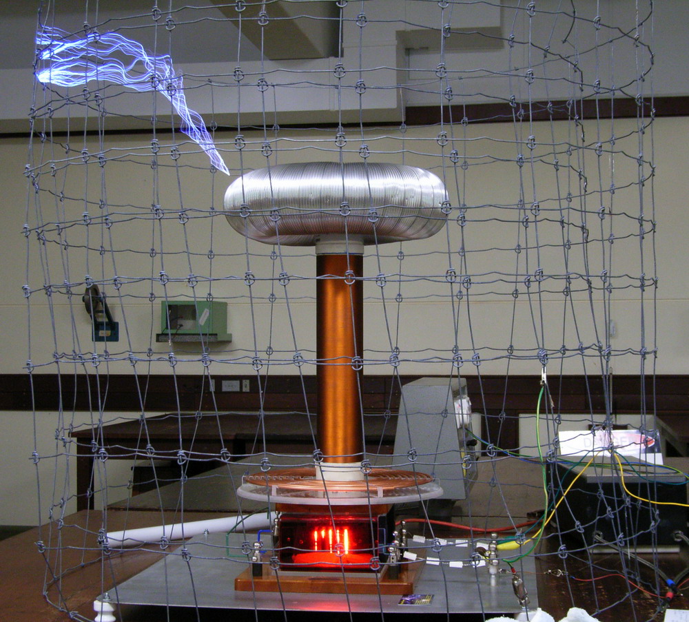 Sparks are 36 inches but it does need to be contained with smaller sparks in a Faraday cage for public safety. I have also made it on a large aluminium sheet counterpoise to allow operation in a non earthed environment.
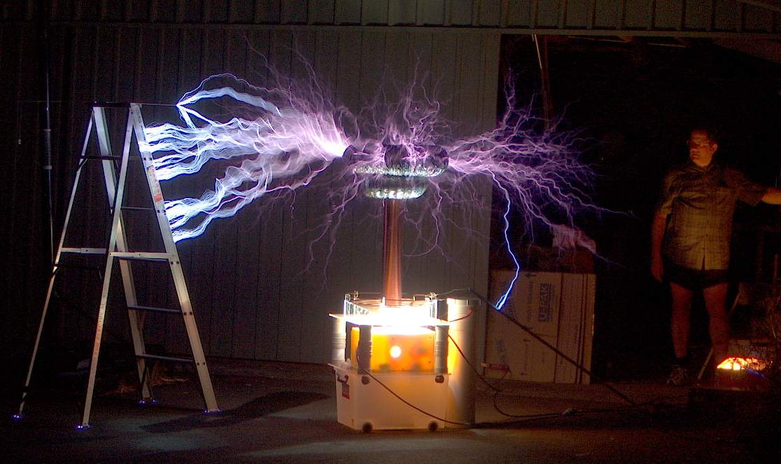
Early testing and demonstration without a cage. The cage is to reduce radiation and for safety.

The spark gap behind the red acrylic. A fan was added later.
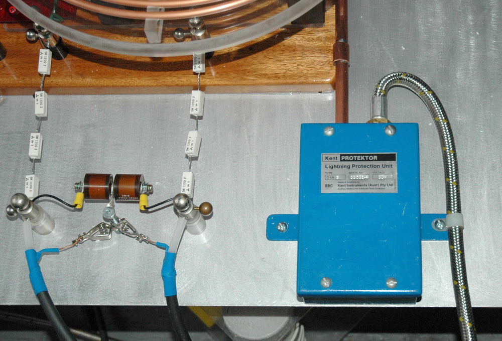
There is a fully shielded MO interference suppression circuit in a commercial “Lightning Protector unit” which I have modified and is used for the spark gap fan. There is a “Terry” filter of sorts with 360 ohms 15 W and a 440 pF 40 kV cap on each leg of the HV. HV leads are heavy 75 ohm coaxial cable with shield present.
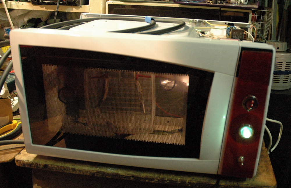
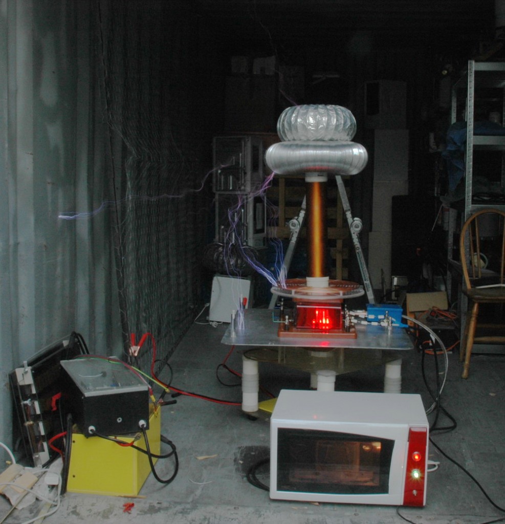
The modified microwave oven shell to contain the power supply and control circuitry safely.
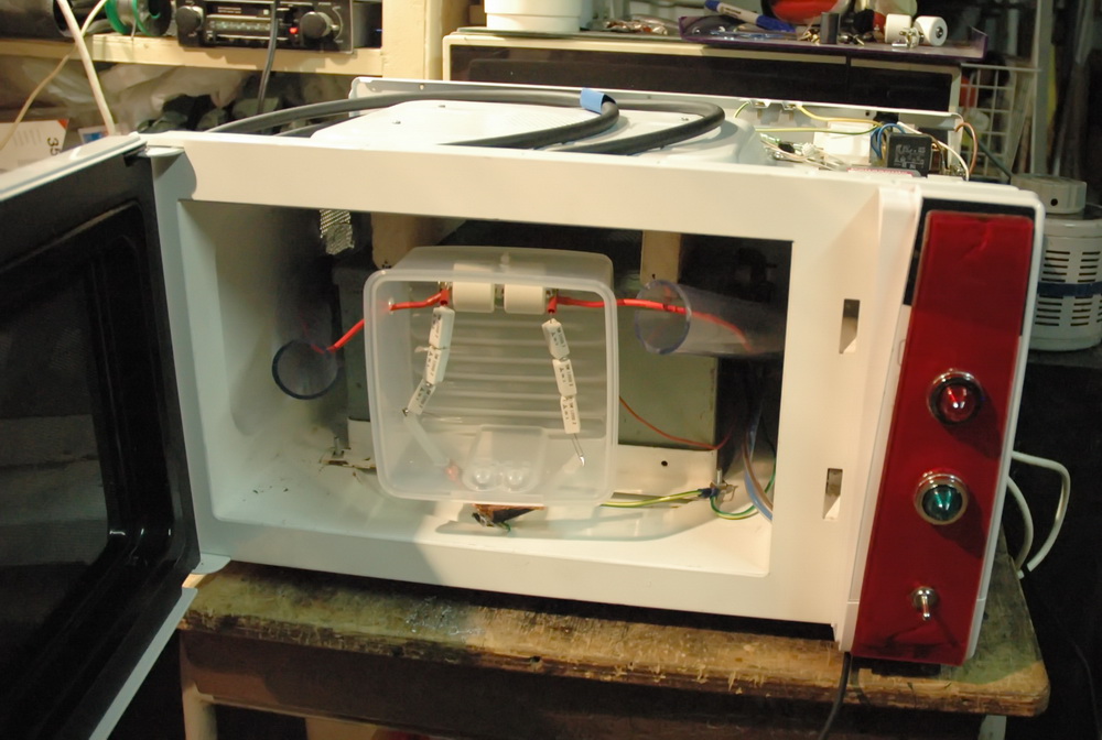
Above shows the power supply which is a 12 kV, 110 mA NST which I have crammed in to a microwave oven (MO) shell.

I have added a solid state relay (the red internal light), large front indicator lights and front switch. There is a remote switch with a flashing red LED on a 6 foot lead. It uses the original MO mains interference suppression, 5 V supply, light, fan and lock out switch when the door is opened.
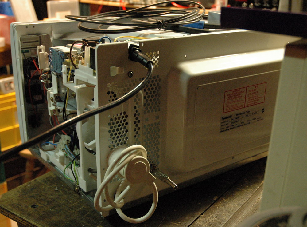 There is a switched mains outlet which can run the fan for the coil and also have an optional variac inserted. There is an inrush limiter and a few MOVs in different areas. I have included a 3.5 mm headphone type socket which requires a shorted 3.5 mm plug to be inserted before the unit will activate (in lieu of a key switch).
Above: The Physics Dept Tesla coil with 15 inch sparks from a 12 kV 30 mA coil. The coupling and tuning was wrong and there were some potentially destructive racing arcs along the secondary.
Above: a 36 inch spark from the 16 inch secondary using a 12 kV 110 mA transformer. It is a daytime shot hence the sparks are low contrast. There was an extra toroid to give extra capacitance as it had been tuned for use with a Faraday cage.
I found this demo of this coil without cage giving some shocks to a girl. They seemed minor but only because the coil is detuned being out of the cage. I disagree with this from many points of view including potential risk of lethal shock if she drops the fluoro tube down onto the primary where she could be exposed to 12 kV at 110 mA.
Related pages
Try something else
External links
Photo Date: Feb 16, 2006
