 This variable frequency flyback supply 4 kV AC was built after it was mentioned the Physics Dept needed a variable 50 -100 kHz sine wave supply between 1-2 kV.
“Continue reading” for more details and photos.
The load is 140 pF and it was to be used to test resonances of a sapphire mirror for a laser interferometer in a gravity wave detector. I used a simple circuit with a 555 oscillator driving a MOSFET. This drives a ferrite transformer which was from a microwave oven inverter power supply and puts out about 2 kV. Not technically a flyback transformer but similar. I rewound the primary to 10 turns. Once driven by enough voltage (about 37 VDC) it puts out about 900 VAC RMS into the capacitative load. This is about 20 W or more even with no additional load. Since the input waveform is a switched half wave, it has a lot of harmonics. This excites the resonance of the capacitor load and the coil at perhaps 200 kHz. I have smoothed the output by using a resistor. Because this is near resonance the resistor takes a lot of the output and the 4 x 10 W resistors get to 160 C.
 The load resistors are shown and also a voltage divider to allow a CRO to be hooked up.
 The set-up is housed in an old variac case which has room for the transformers.
 From Uzzors drivers page of Eirik’s flyback driver
 The spark at 22 kHz is about 5 kV peak (left photo) and can be drawn out.
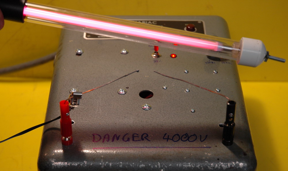
Voltage at 100 kHz is about 900 VAC RMS but still enough to draw an arc and heat wires. It lights a nearby neon as well (right photo). And, no, those low voltage terminals don’t stand up to 5 kV long.
 Waveform at 22 kHz
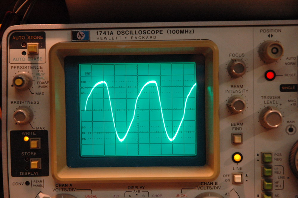
Waveform at 100 kHz. The smoothed resonant effect is evident at 100 kHz where the waveform is more sinusoidal. I have let the smoke out of a few IGBT’s and MOSFET’s during testing.
The lack of a sinusoidal output meant it was not helpful for the Physics Dept.
Related pages
Try something else
 Tritium tubes
External links
Photo Date: June 24, 2007