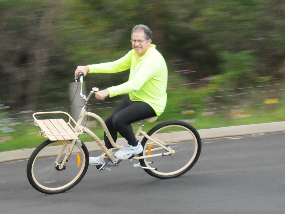
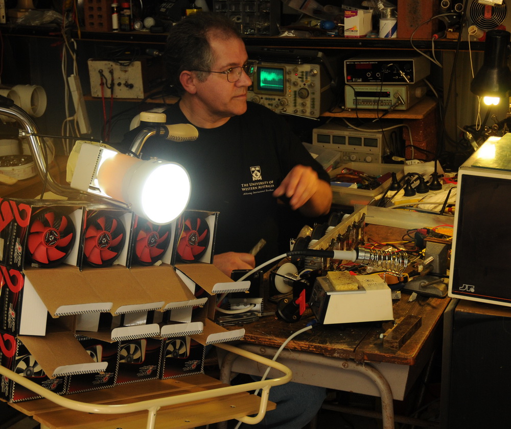
 Planning and early stages of the bike lights construction starts in the shed. Bicycle: Electra, “Townie” ladies bike, cream AU$1300. Chosen by my wife. Ladies bike??? Big advantages of being able to step through and sit on the seat with feet flat on the ground to support the high center of gravity of the battery weight. The front tray is a big plus as well. No point in trying to make a heavily loaded racing bike or mountain bike I reckon. Old lady retro feel styling in cream. (I wanted the purple flowery one but my wife was firm). It has 3 internal hub gears and back pedal brakes. And it has a bell…
For more details and photos:
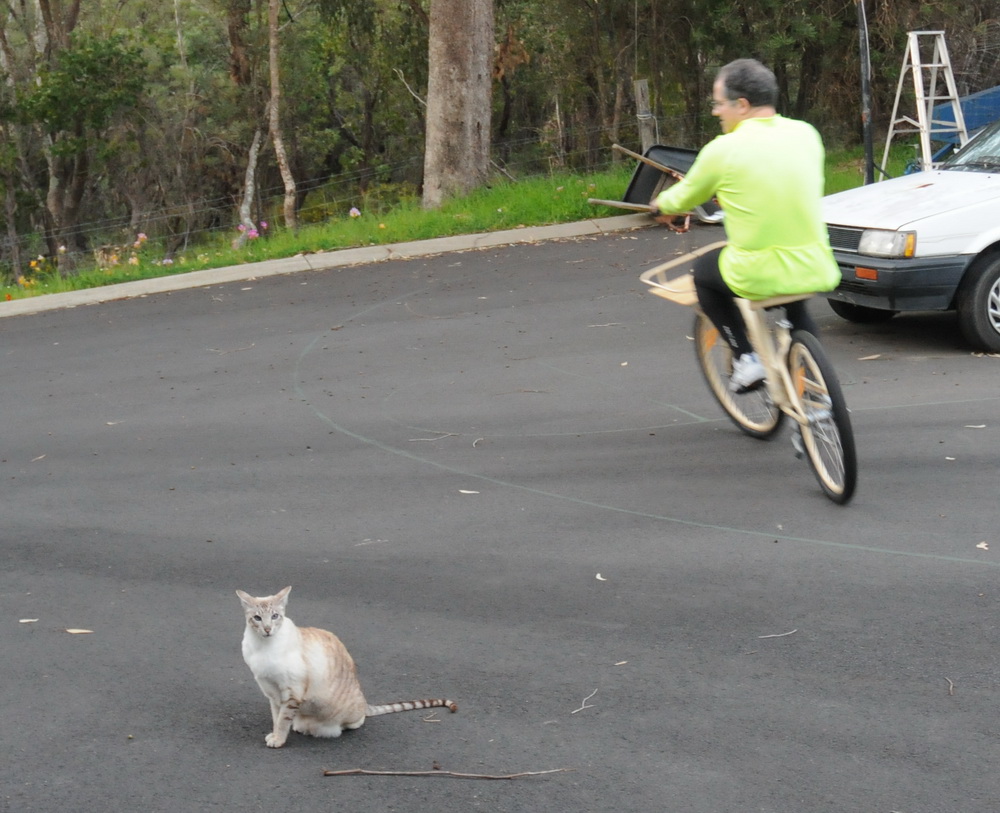
Our cat and it’s WTF expression on first ride of the new bike. Cycle outfit is from my daily ride home on my “normal” bike. Batteries: Three 35 AH Absorbed Power deep cycle batts . These are like car batteries but with better construction to allow greater discharging. From the data sheet, these are good for 12.2 V 35 A dropping to 12.0 V at 12 mins. At 70 A, 11.8 V dropping to 11.7 A at 6 mins. Need 3 batteries to run 34 V at 52 A peak (1.8 kW) delivered to LEDs ie need to drop from (12.0 x 3=36) 36 V to 34 V. 2 V drop at 50 A is barely enough for heavy duty cabling and some big MOSFET’s to do pulse width modulation (PWM). This is all a bit on the edge and will call for some tricks.
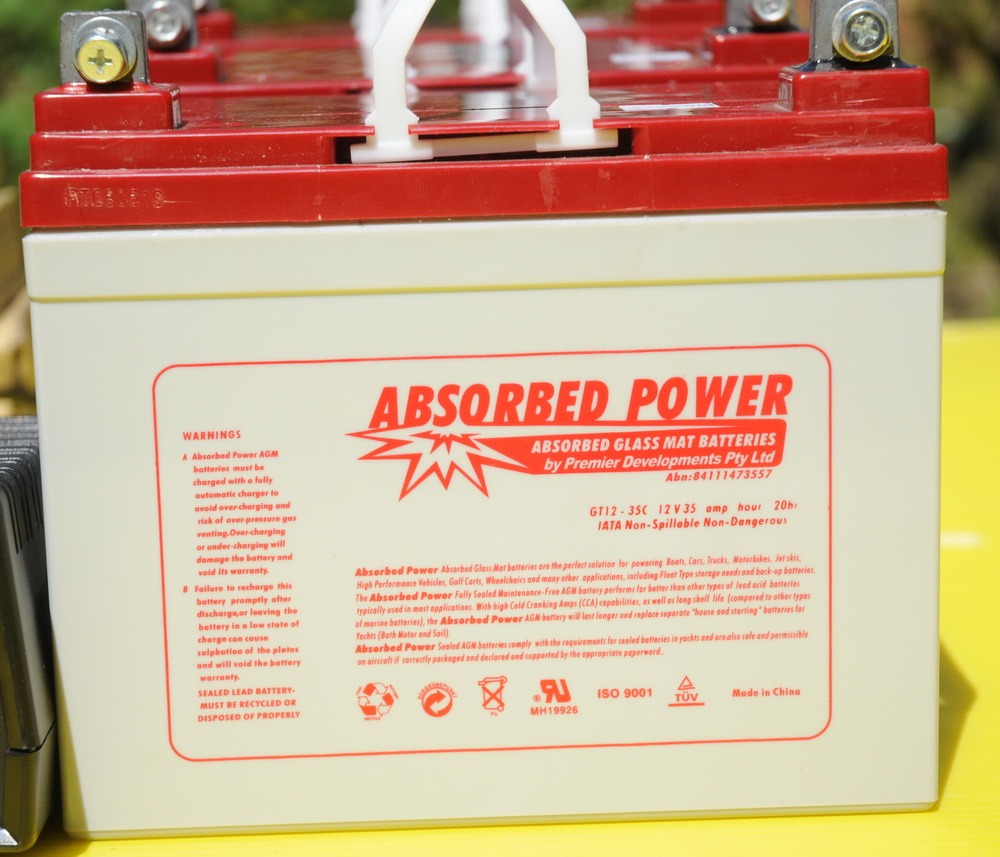
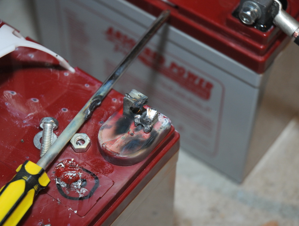
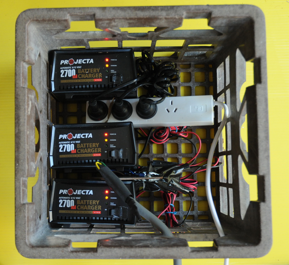 The left photo shows a battery close up, center photo shows shows what happens if you accidentally short circuit them while using a screwdriver to tighten a terminal and the right photo shows the three 2.7 A chargers. Front LEDs From eBay of course. Led-world2007 is the place I use.
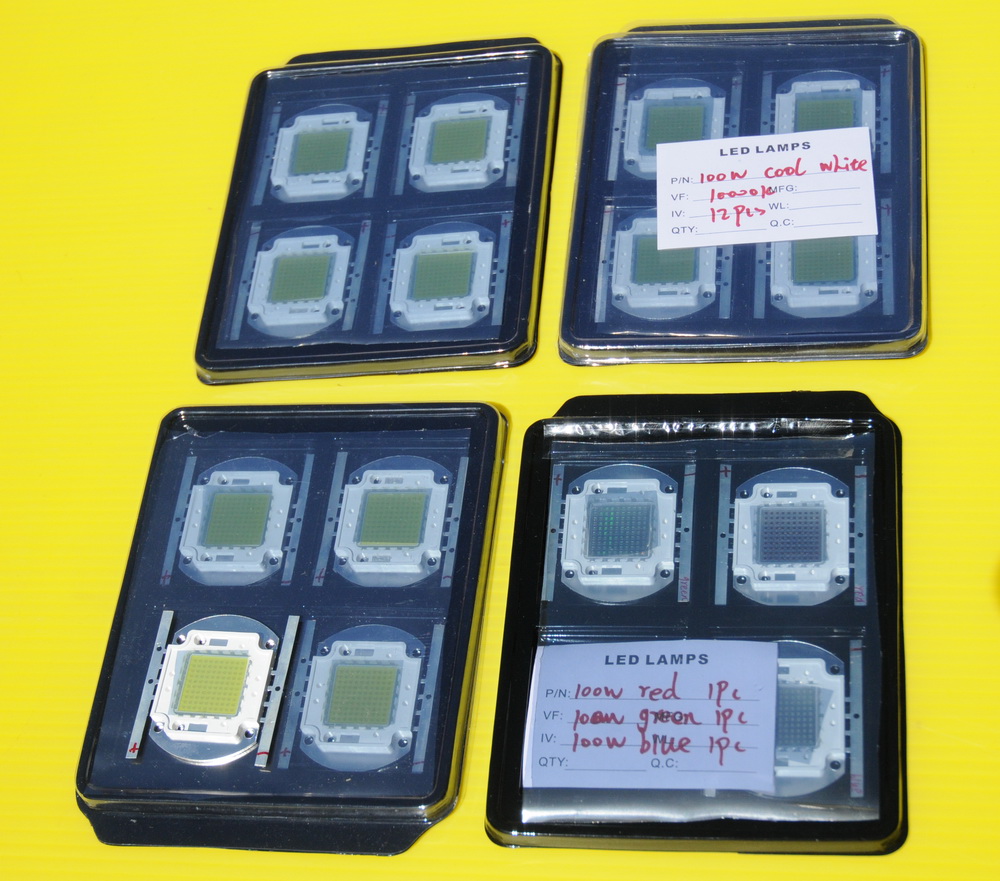
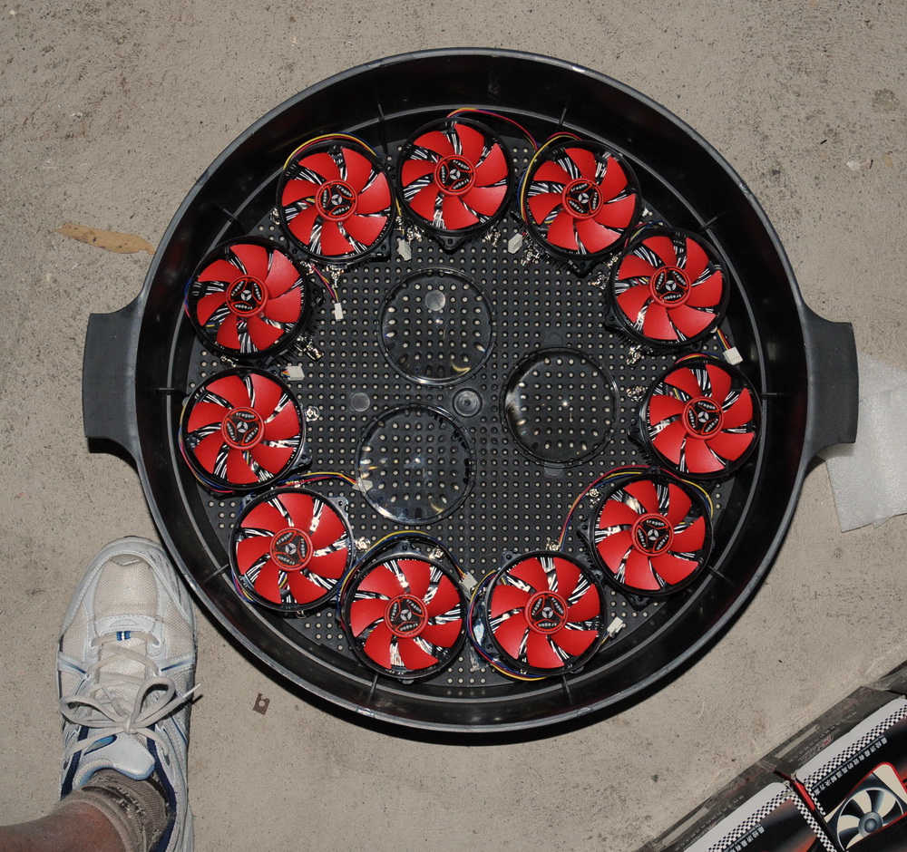 My original plans were to use 11 x 100 W LEDs. Rated at around 34 V (32 – 36 V) at 3.5 A (3.2 – 3.8 A) with luminous intensity 6000 – 6500 lumens from a 1.8 cm x 1.8 cm surface. Roughly 10 Watt light output by my calculations and hence have to lose the rest (90 – 110 W) as heat hence the decent fans. In addition to the forward facing 11 white LEDs there will be 3 coloured LEDs (Red, green and blue all 100 W 6000 lumen) facing forward to a total of 14 LEDs facing forward ie 84,000 lumens. The 3 coloured LEDs in total will be white but will allow me to run them separately to generate any colour. For info on white 100 W LEDs see 100W LED page about it. These will be cold white 9000 – 10,000 K colour temp like those annoying expensive blue Xenon car headlights. The LED ballasting is a complicated issue. LEDs are best driven by a constant current driver since the voltage drop across them is fixed and any attept to use a higher voltage will raise the total current dramatically. On small LEDs a simple resistor is adequate but this is not really suitable here. While a switchmode buck convertor is ideal, there were cost and design considerations and a short timeframe. Accordingly I have chosen to use a resistive ballast as is used with small LEDs. Rather than a straight resistor, I have used 6 V 18+18 W globes as a combination ballast, current stabiliser and fuse all in one for each LED where it has to drop 6 V max. Globes are a non-linear resistor that has a very low resistance at startup when the filament is cold. Think about it: 3 amps almost constant current, no heatsinking problems. Anyhow, much better than a resistor. Now I just have to go and raid a lot of Kombie taillights… Actually sourced these from Delhi (6 V vintage motorcycle globes). As an example, I recorded a peak current inrush of 6 A into my green LED today (rated 3.4 A) then settled nicely at 3.1 A using a 12 V 100 W globe which only glows to red heat. How ironic to use that as ballast for a 100 W LED! Peak pulse rating for a 1/10 second pulse is 5 amps which is about 50% over continuous rating.
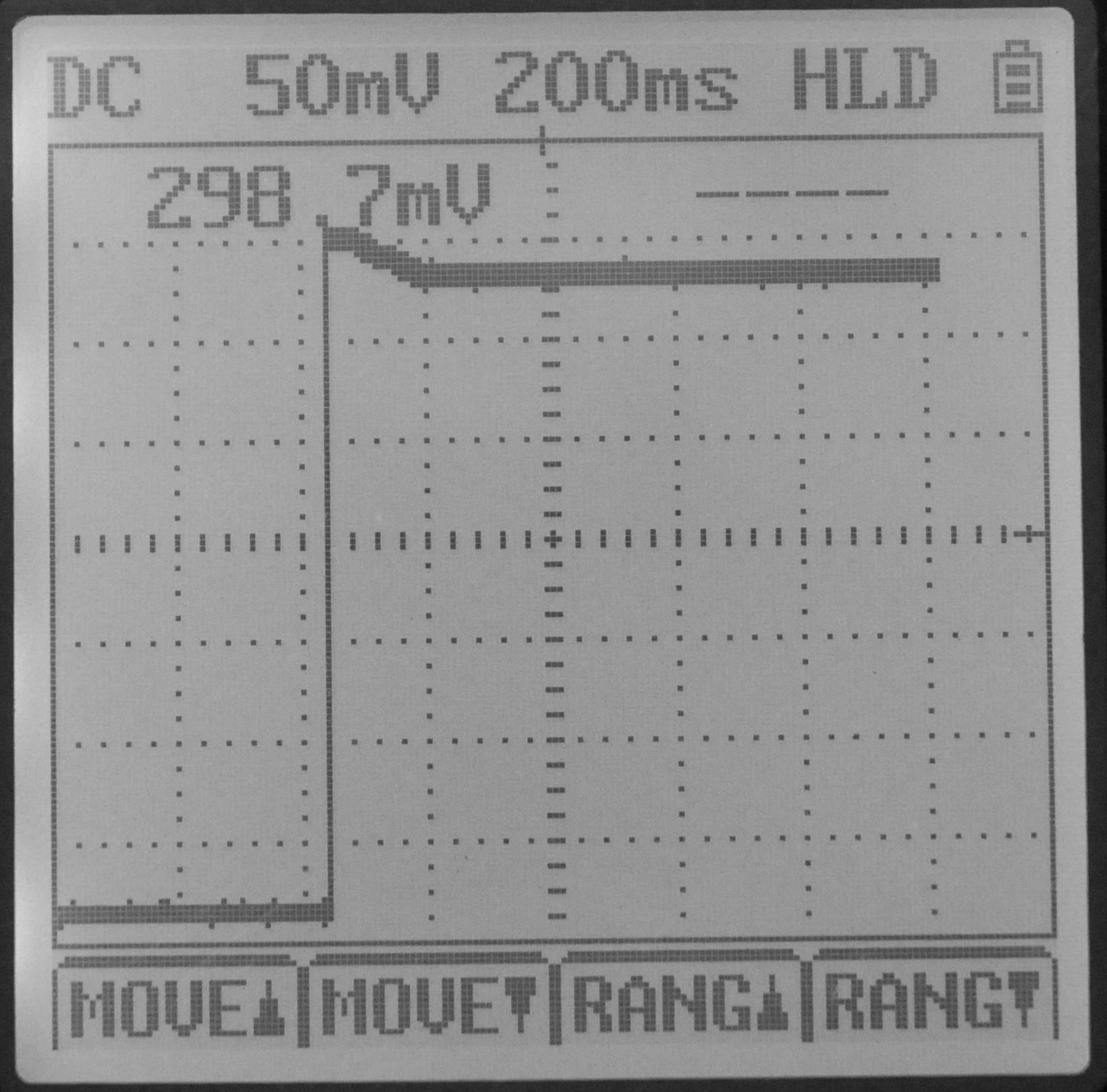
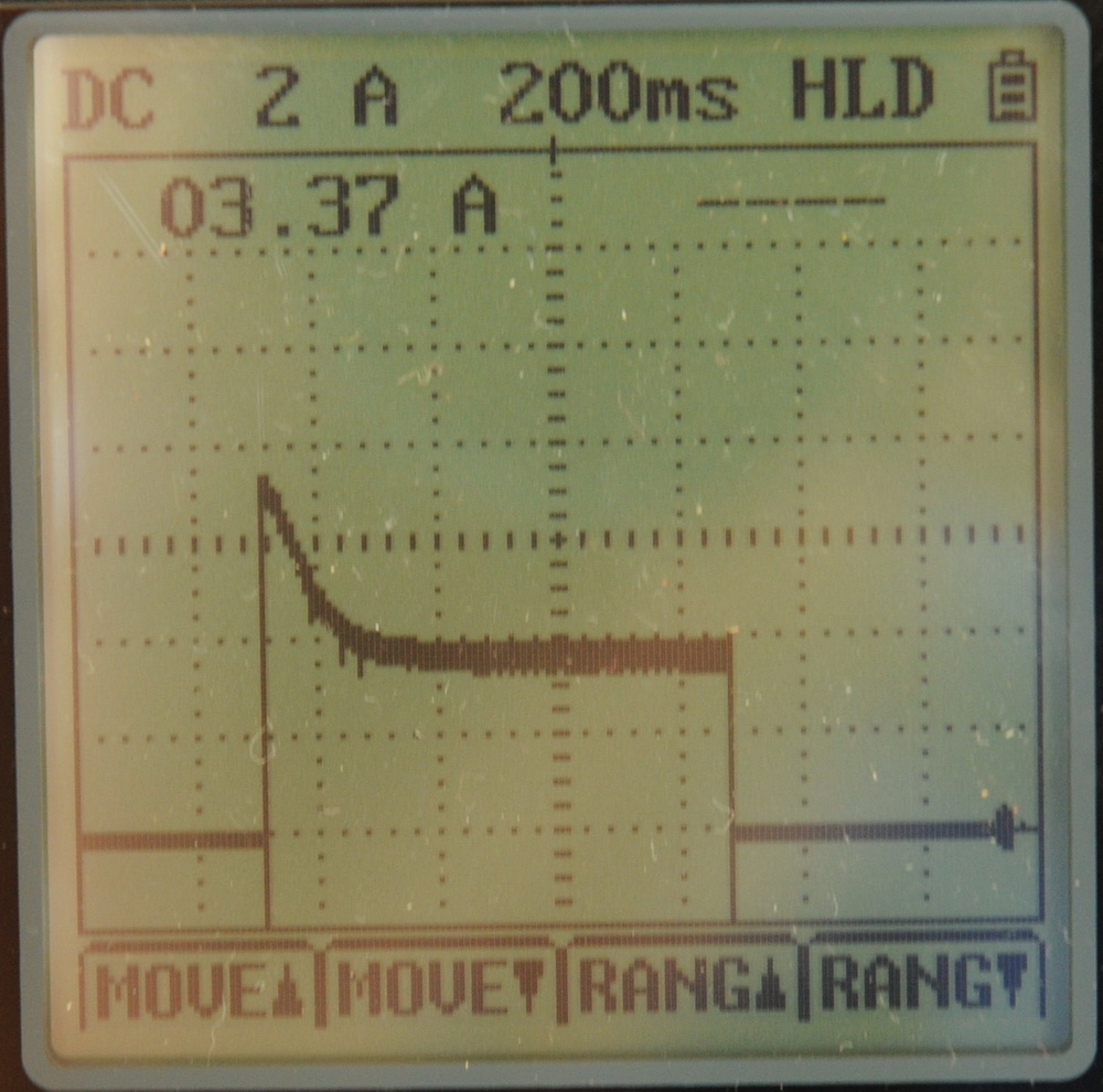 The left photo above shows the output of a photodetector taken at switch on of the white LEDs in the final array using a 6 V 18 W filament as ballast. Note the 5% increased light output at switch on which tails off in the first 100 ms or so as the light globe ballasts heat up. I had thought it might be greater. The right photo shows the current at switch on is almost 100% greater at 7 A reducing over the next 200 ms as the filament heats up. It suggests that I am running the LEDs (at least a single LED with a full battery charge), close to its maximum.
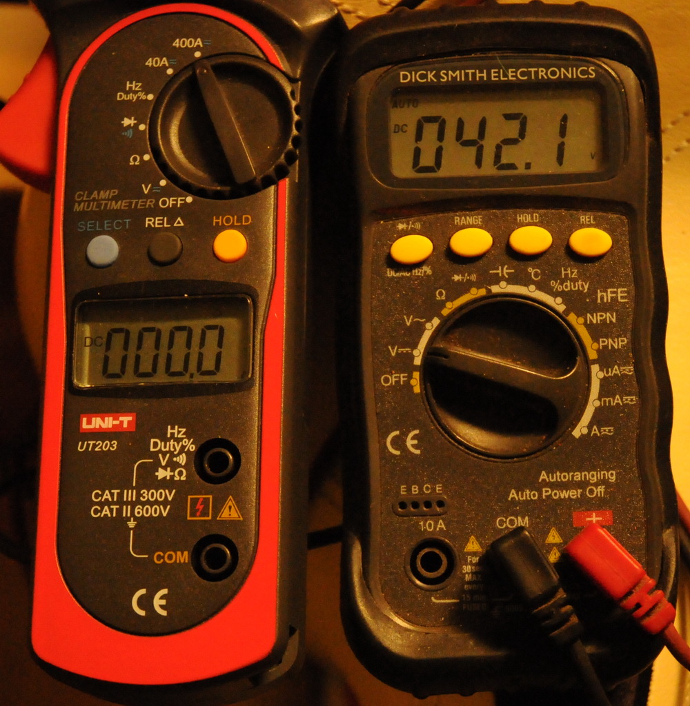
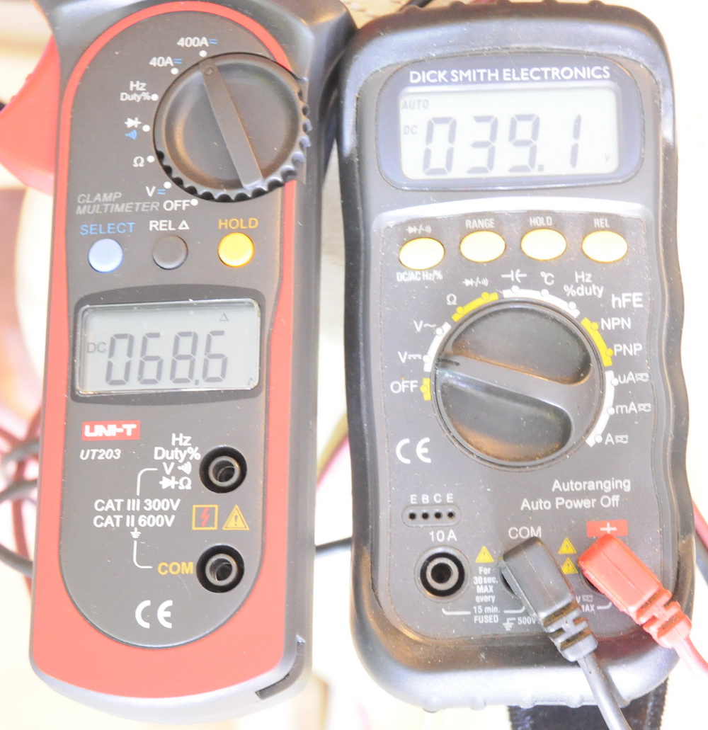
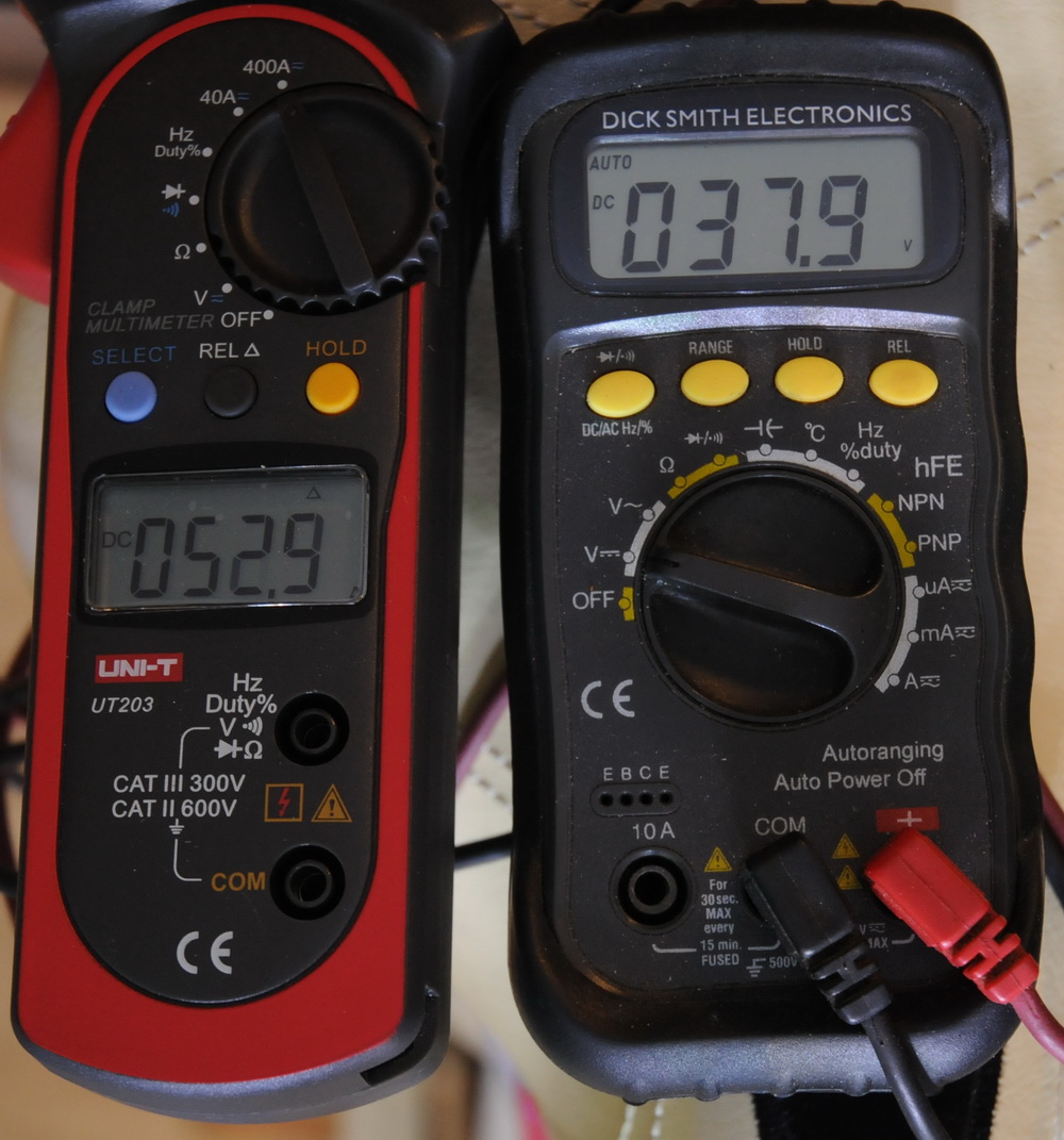 Here are the current and voltages at switch on of all 18 LEDs on the bike. Peak is 68.6 A (3.8 A per LED) which settles to 52.9 A (3 A per LED) 2.0 seconds later. Peak power is 2682 W settling to 2004 W.
 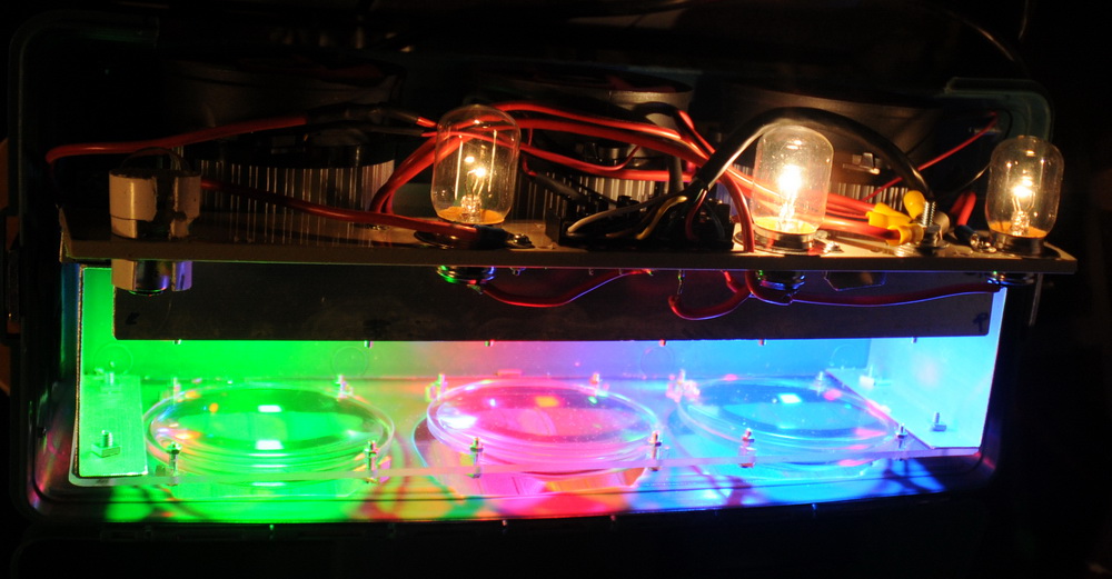 The red LED uses both filaments of the 6V 18 W+18 W to drop 12 V, plus a 1.5 ohm 15 W resistor to drop a further 4 V, whereas the blue and green use one of the filaments only. I have a later option to switch in the second filament if the main voltage sags too much under load. Here is an alternative source for 100 W LEDs and specs. Snowdragon.
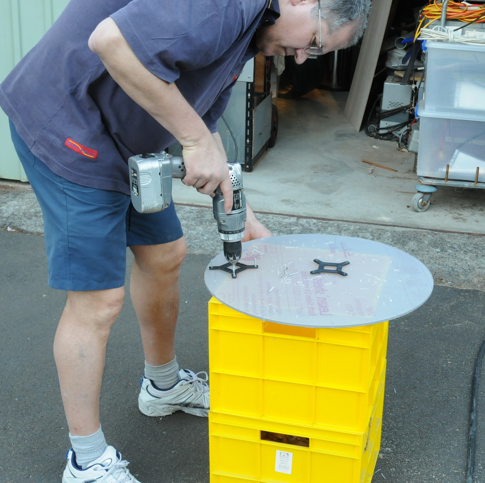
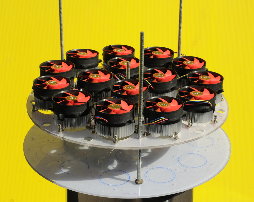
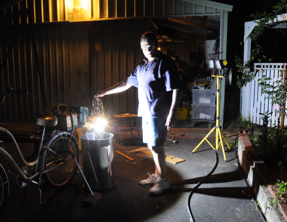 The left photo above shows me starting the front array construction, center photo shows how the fans will sit and the right photo shows first light of a single 100 W LED. Note the weak 150 + 150 W shed lights.
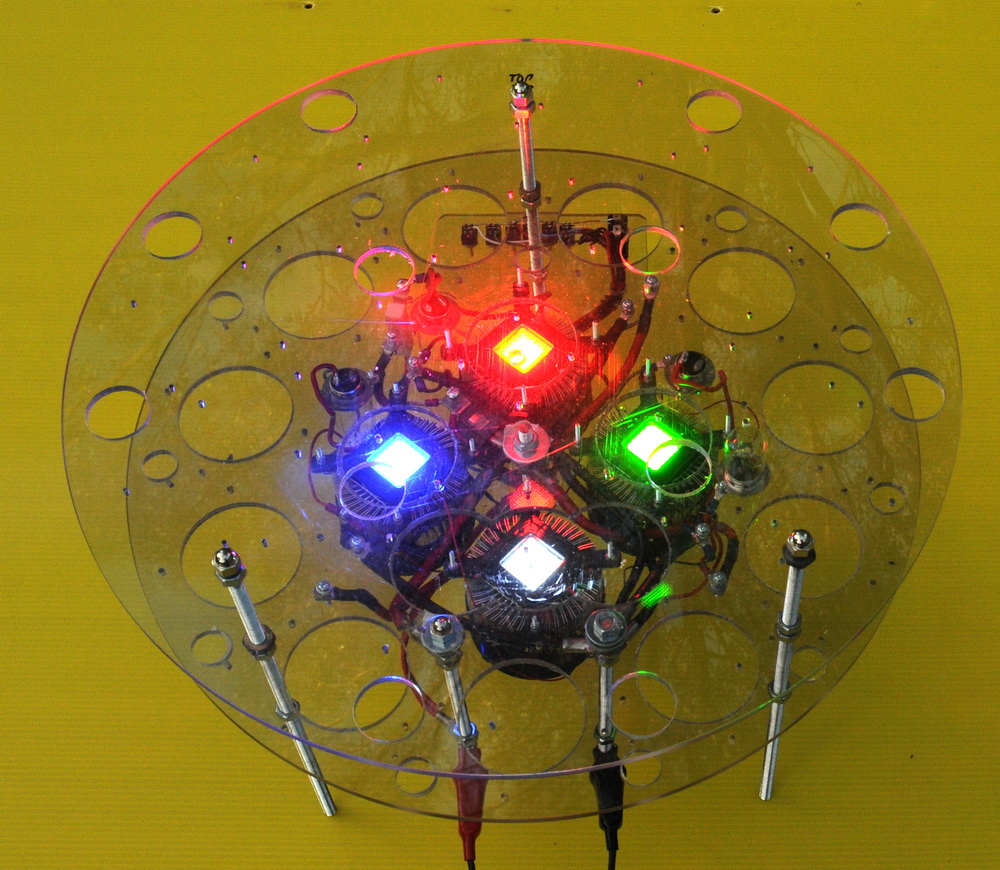
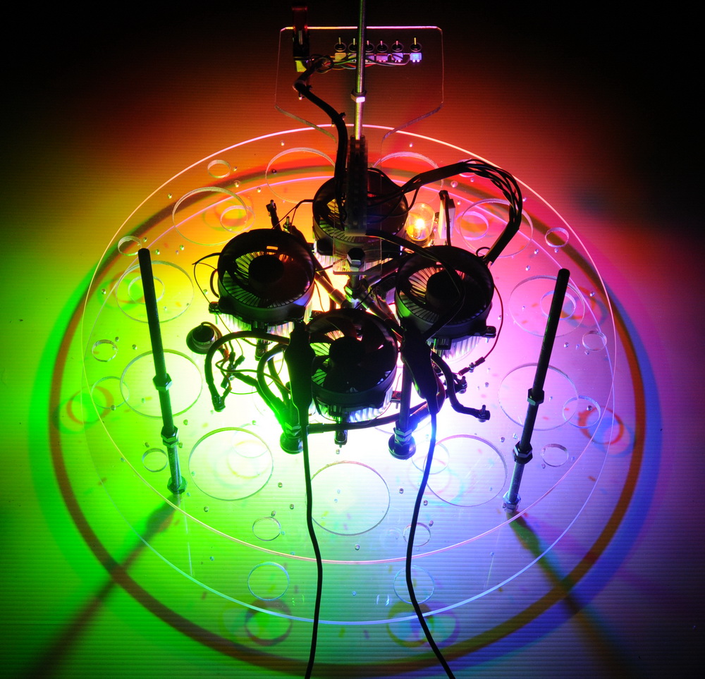
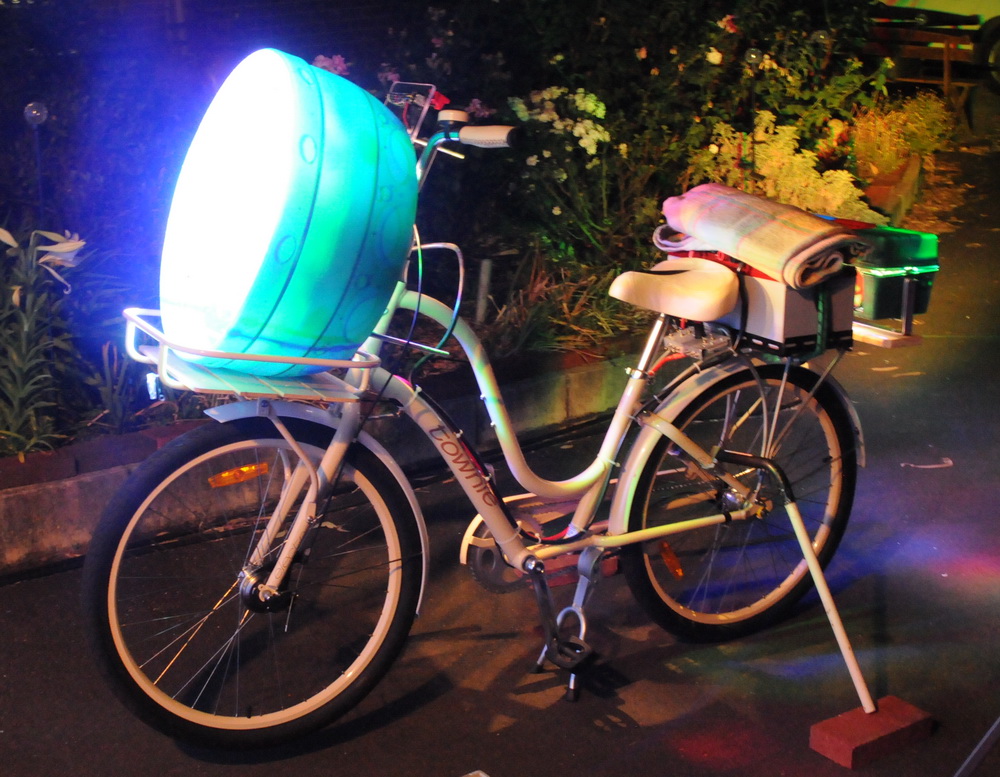 The left photo above shows the front array construction with red, green, blue and white LEDs at low power. Center photoshows the rear view with the rats-nest of wiring becoming evident, and the right photo shows first light of the partial front array on the bike. “Only” drawing 700 W at this stage out of target 2000 W. Controls The rear control box which includes a 100 A keyswitch (1000 A peak) plus 6 switches for switching the rear lights (3 to control RBG independently plus one for road safe red stop light plus one for PWM dimming plus one spare). There are another 5 switches to control other 12-36 V functions as I might decide later.
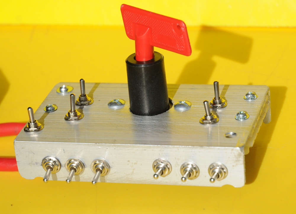
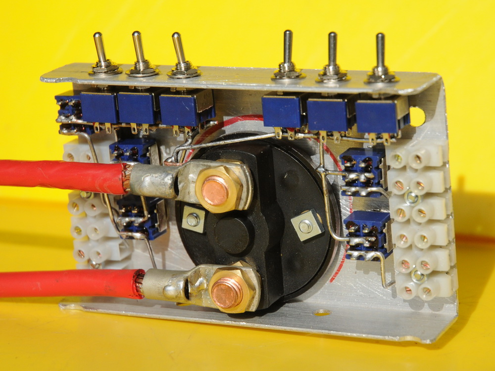
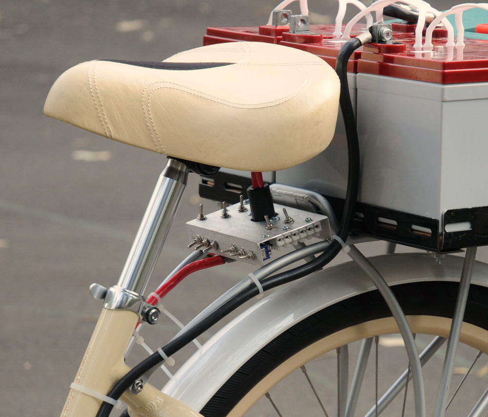 So far only RGB switching basic capability at present. Rear LEDs Three coloured LEDs in the nominal 100 W and 6000 lumen range. If you believe the source data. Or if you believe a similar 100 W LED manufacturer then red 88 W 3500 lumen, green 100 W 5000 lumen and blue 100 W 1200 lumen average. Bear in mind that lumens relate to the eyes sensitivity at that wavelength – greatest for yellow, least for blue. These are facing backwards. ie approx 10,000 – 18,000 lumens to the rear as well. The colour gives capabilities of, for example, a red brake light or a flashing red and blue police light, or a smoothly colour changing light etc. This gives it more variety by far. And it gives crazy shadows…….
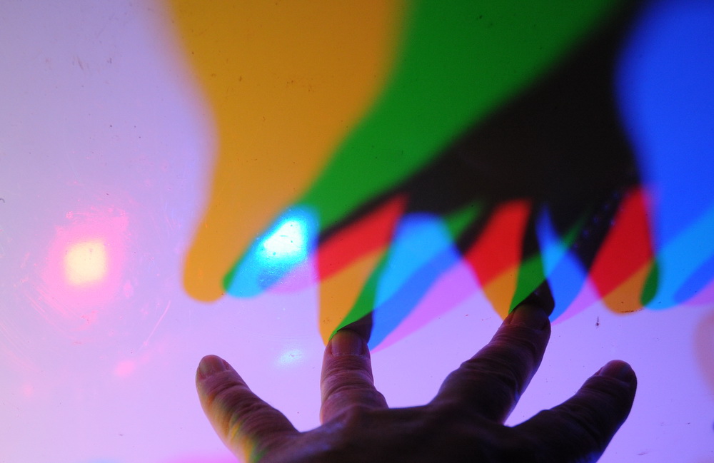
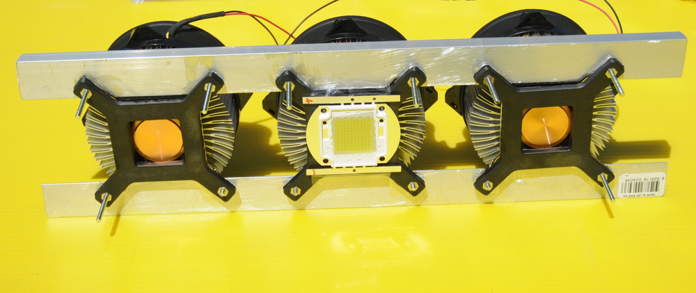
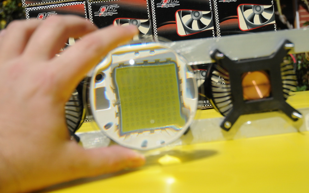 The red green and blue lights above left give really colourful shadows as the primary colors mix. The basic LED mounted onto the heatsink is shown center and the effect of the lens shows the fine detail of the 1W 10 x 10 array of LEDs on theright.
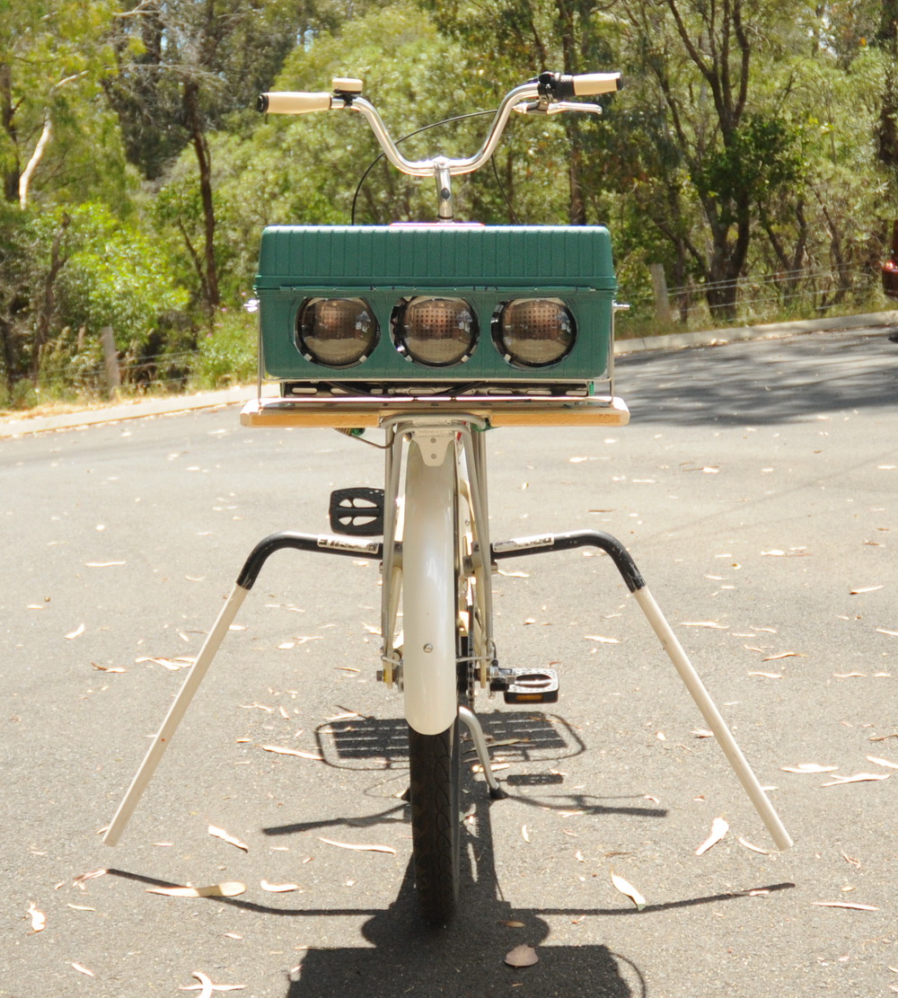
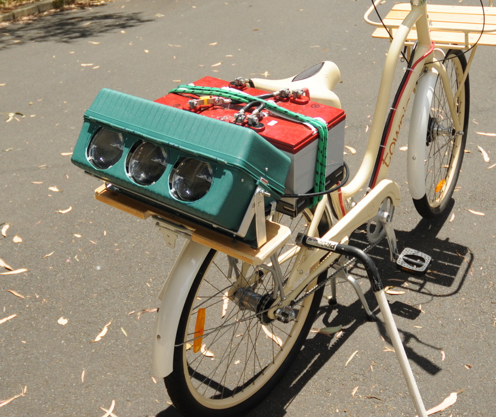
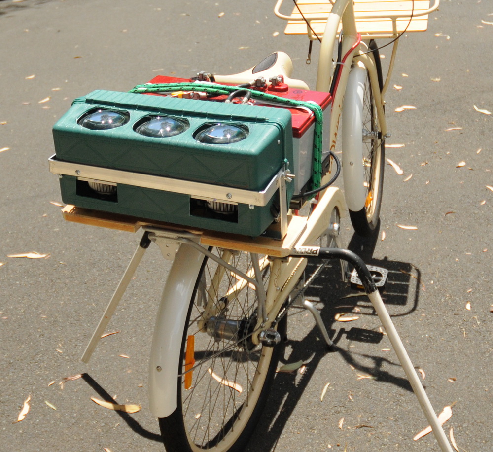 Above shows the mounted LEDs in the rear array which can be tilted vertically (for the Xmas tree project). The plastic toolbox is an excellent fit for the red, green and blue rear lights fans and optics. It is compact and I will be able to swivel it as well.
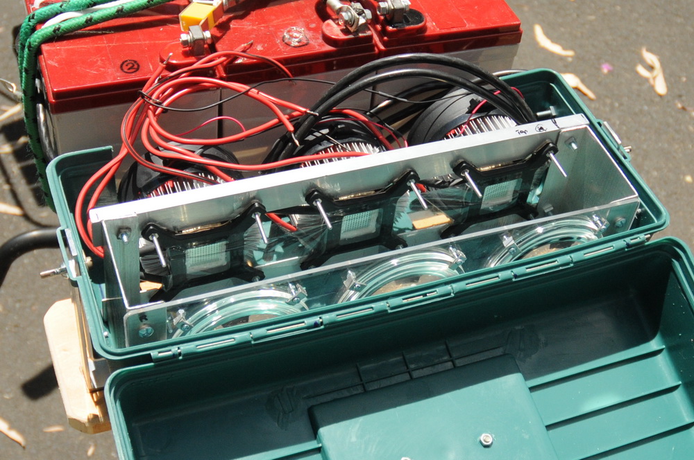
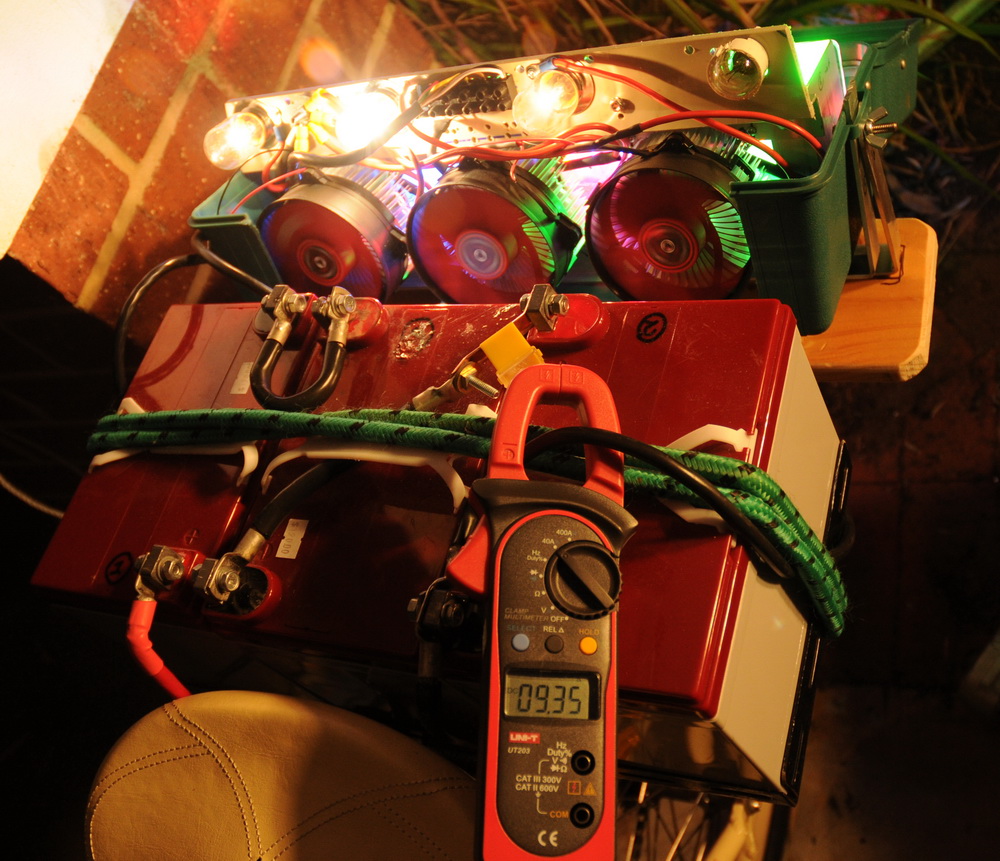 Above shows the as yet unwired rear array. The center photo shows current of 9.3 A 37 V = 344 W. Love this clamp meter with 40 A DC scale – bought it especially for this project. Ballasting of the Blue and Green LEDs is via 6V 18 W globes. The Red LED runs a lower voltage so has 6 V 18 + 18 W plus a 1.5 ohm, 15 W resistor in series.
 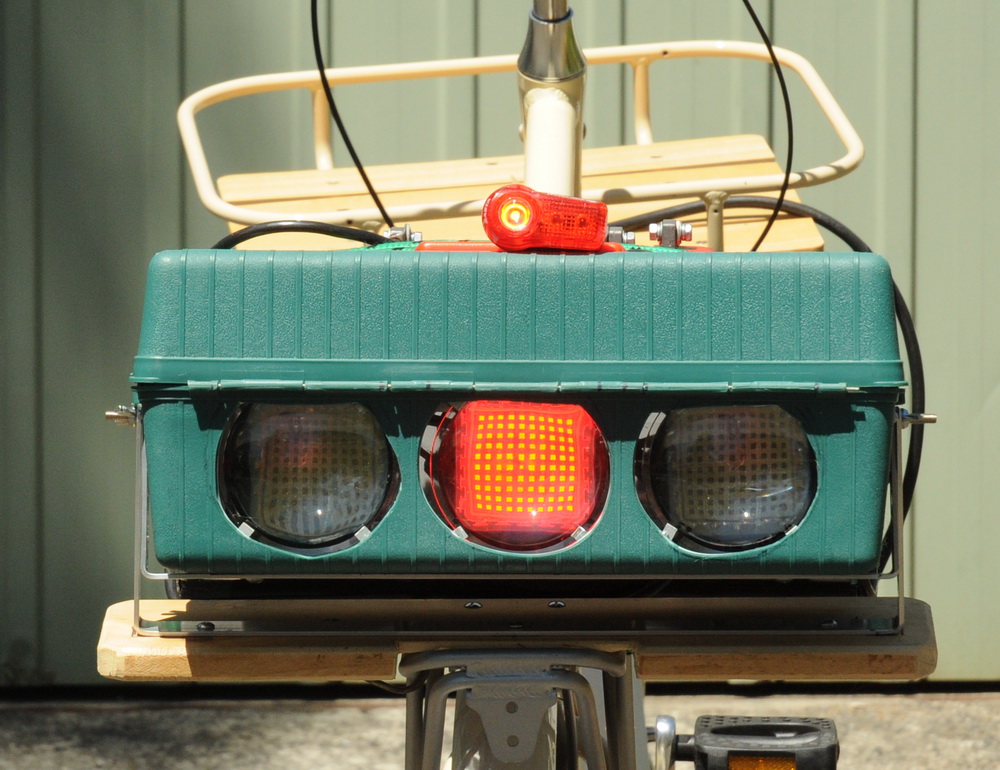 Above shows the low power (2 W) tail light riding mode with a normal tail light for comparison. Keeps it street legal (maybe). You can see each of the 1 W LEDs in the array. I also have a low power 10 W front light mode. Electronics At the moment I have simple switching but my plans are for more electronic control. I have a PIC driven MOSFET motor drive kit for 40 A at 24 V which I will adapt. to rate 70 A MOSFETS’s x 4 in parallel are IRF1405’s. 55 V 169 A. Peak voltage is a bit close but nothing much inductive here. The front RGB LEDs will be switched into the main PWM or onto an individual circuit.
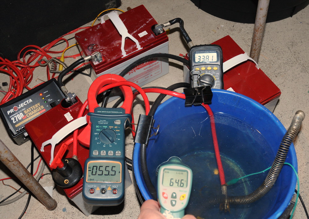 Left photo above: Every man needs his shed… Right photo shows a battery power test. The meters above, read 55 A, 33 V and water coolant 65 degrees C during a power test. It took me a bit by surprise that the bucket of water reached almost 80 degrees C and I had to dash out to get more cooling water. That’s what 1800 W does. Heatsinks, Fans and Lenses Each LED needs to dissipate about 90 W of heat, similar to a modern CPU in computer. These fans and heatsinks are low weight but effective. The bike uses 15 of these in front and 3 in the rear.
 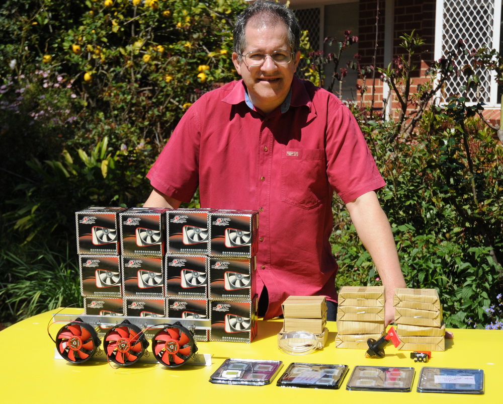 The 10 cm diam glass lenses need to be about 10 cm from the LED to focus to 10 degrees so you will lose some of the beam to side scatter. I want a tight 10 degree beam in front and a wider beam in the rear. Again from Led-world2007 . Later I tried a large fresnel lens to see if I can tighten the beam more but without benefit. Mechanical supports
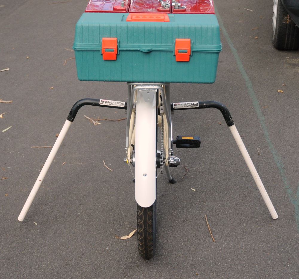
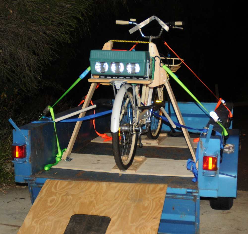 I made an outrigger stand in the left photo, as the inbuilt one would not handle the 33 kg battery weight so high up. I cut up a tri-bar set that I got for a few dollars from a tip years ago. These are extensions to the handlebar of a road or mountain bike out forward for a better racing position for triathletes in particular. Add a PVC conduit and these can provide a good support and can be flipped backwards out of the way when the bike is being ridden. For trailer use a more solid setup was needed in the right photo. Reminds me of the pun: A bicycle can’t stand on its own because it is “two tired“.
 Then I made a battery tray out of perforated angle iron and particle board. Simple, effective and quick. Downside is the centre of gravity is high but it is much more compact and unobtrusive than some other ideas I had. Also able to do the heavy cabling to the front of the bike – needed as can’t afford much voltage drop at all at 55 A+. Black cable had 85 mV and red cable 235 mV including switch ie a total of 0.3 V at full load.
 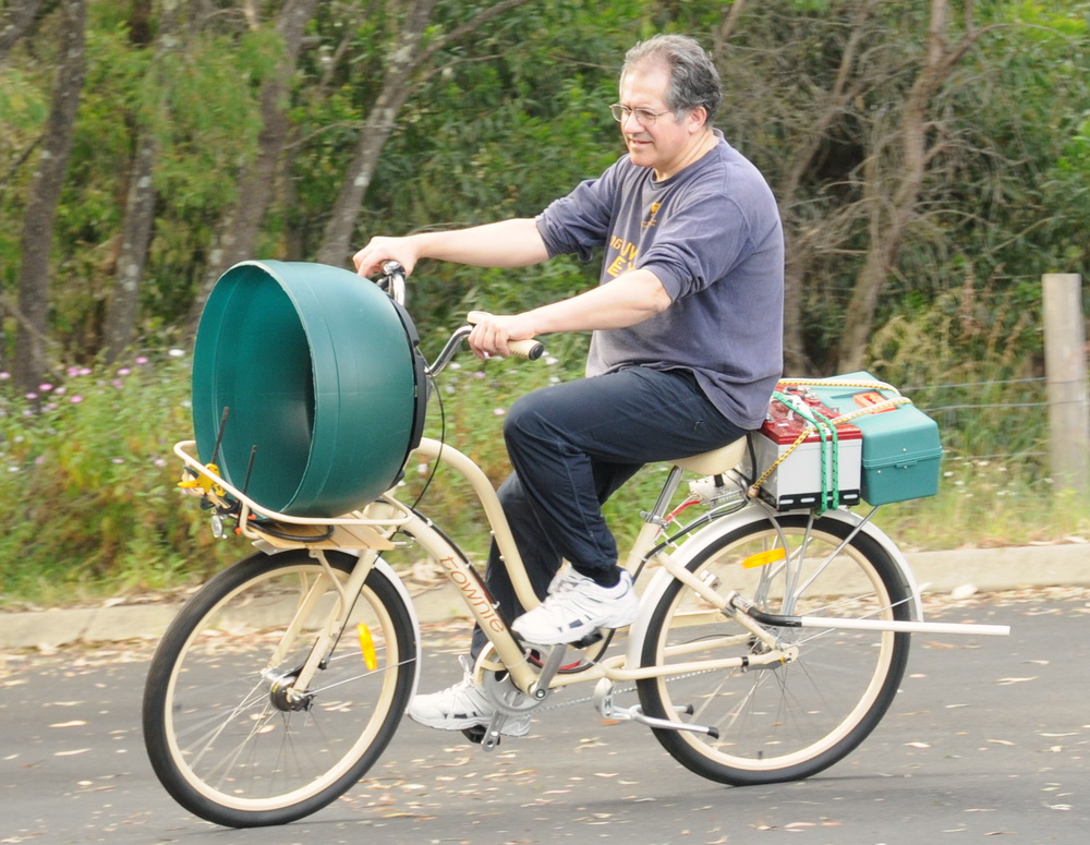 It handles like a tank but is still rideable. But don’t I look stylish riding it! Don’t forget that this is a show bike and not really for much road use.
