A zinc oxide layer can be used to generate RF but just didn’t quite work for me. Yep, failed.
“Continue reading” for further details about this unusual homemade semiconductor.
This is based on an article here where they have been used for a transmitter with a 5 mile range. In essence heated galvanised iron (zinc coated) forms a compound that exhibits negative resistance and hence can be made to oscillate. Zinc oxide is also used in MOV’s and other electronics.
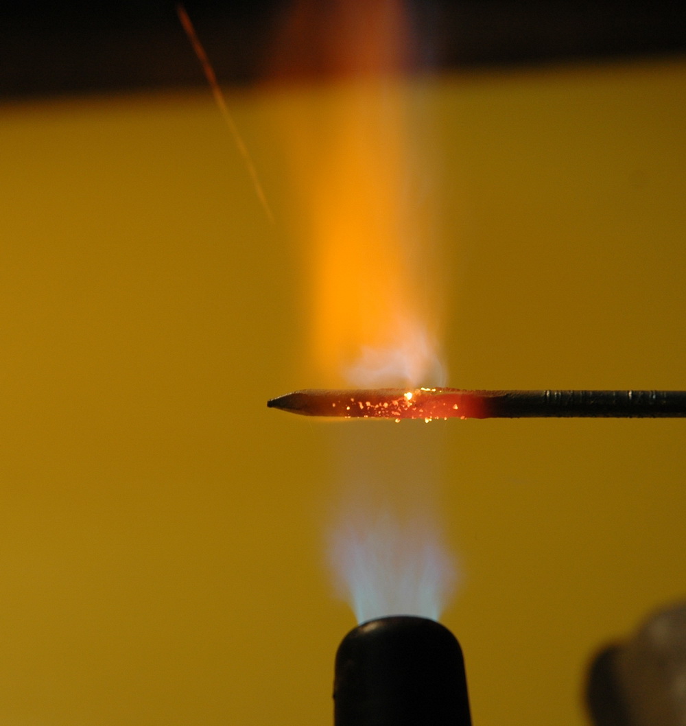
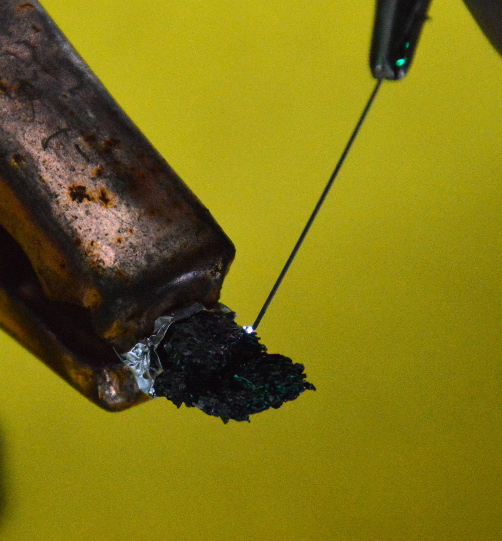
The photo above shows the heating of the galvanised nail until it starts to have sparkles coming off it giving the oxide layer.
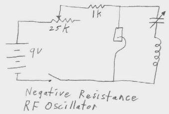
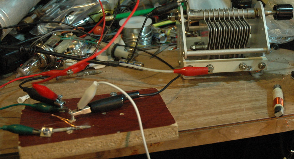
The centre photo shows the basic circuit with a “cat whisker” contact The right photo shows the set-up I used.
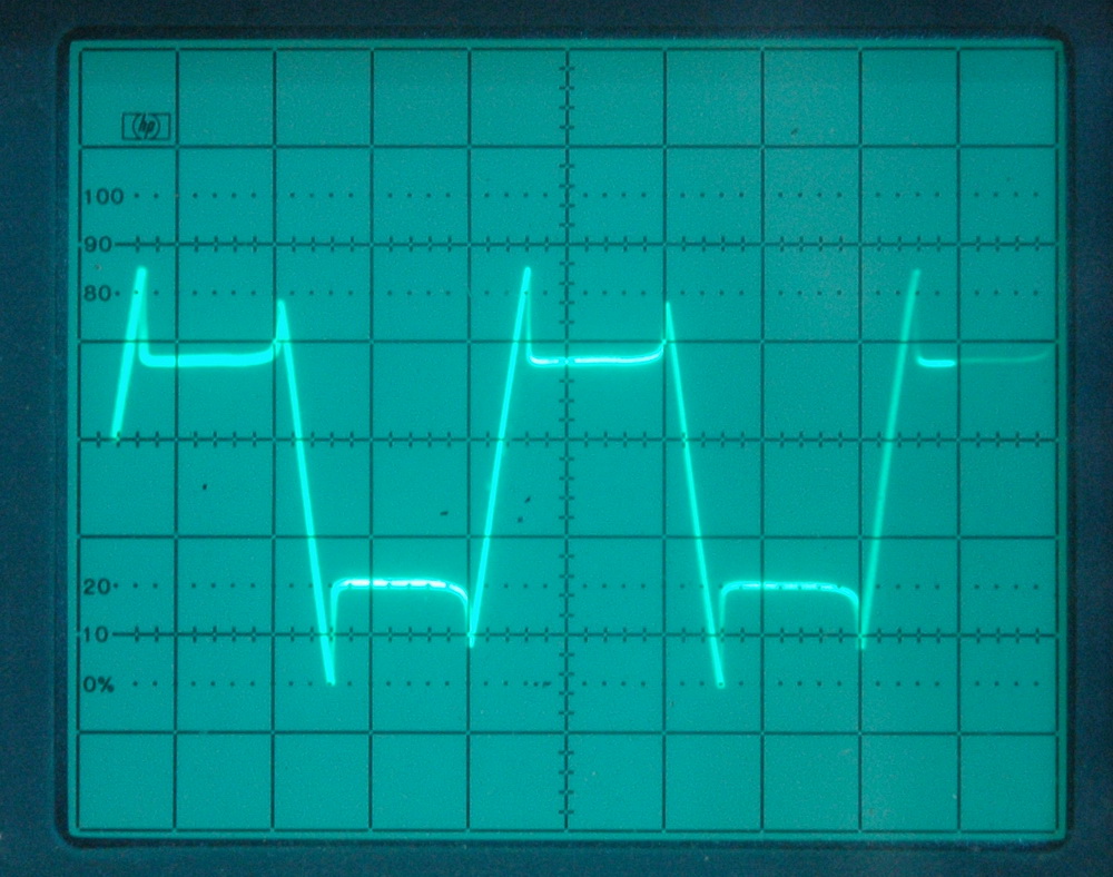
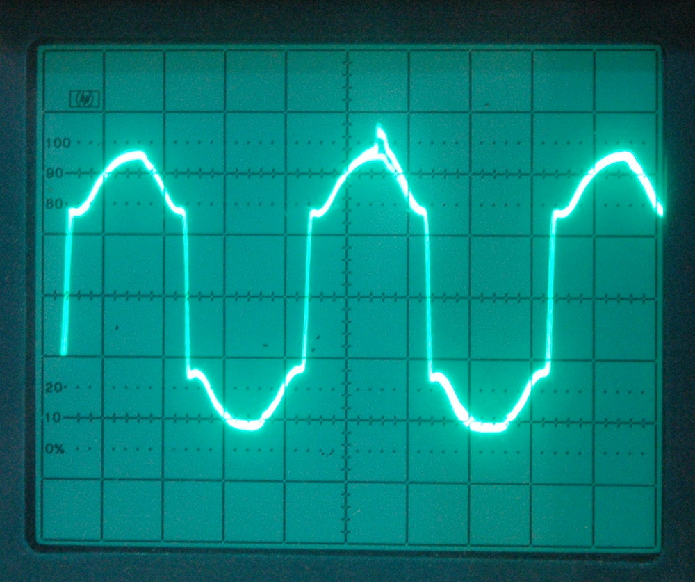
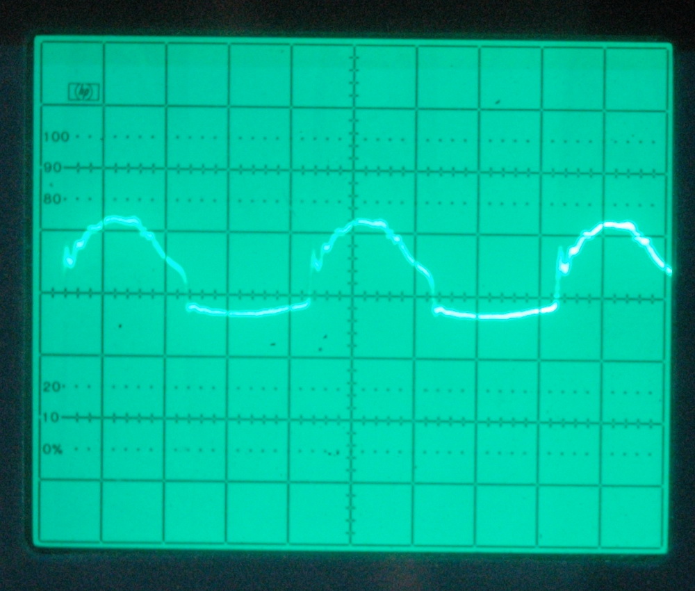
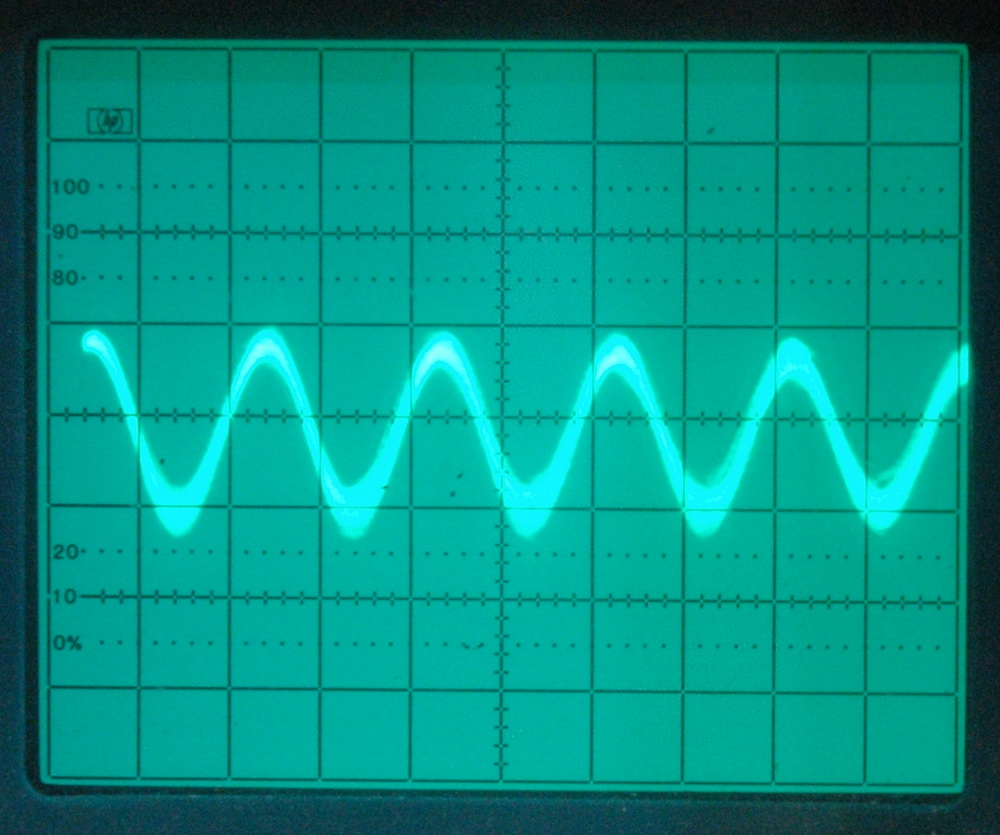
The oscilloscope photos show a variety of waveforms when driven by AC 50Hz. The first two on the left show voltage dependent effects and the third shows some rectification. The last shows some 1 MHz oscillation but it was at very low level and I really wasn’t sure I wasn’t tuning into local AM radio. I never got really stable oscillation with galvanised iron sheet or galvanised nails.
Worth pursuing though. I would love to make a zinc negative resistance oscillator into a transmitter out of copper and zinc only (including the battery, microphone, tank circuit and aerial).
One day ….
Related pages
Try something else
External links
Photo Date: May 31, 2008
