
I was after a homemade rolled cap that would be cheap and reliable enough to use instead of the expensive MMC’s for a Tesla coil.
“Continue reading” for construction details and performance of this capacitor.
The background is that a standard rolled capacitor under oil is cheap but messy and fails readily. I have had many fail.


Typically they are made of two layers of aluminum foil separated by cheap polyethylene sheeting and rolled up then immersed in transformer oil. Electrodes are attached at one end. The right photo shows one with two caps in series internally.
Recently I developed a better understanding due to two things. Firstly an autopsy of the caps showed that they failed on the innermost tightest turns, the furthest away from the electrode wires. Secondly that this could be understood in terms of the operation of a spiral line generator where voltage is multiplied towards the end of the turns by many times.


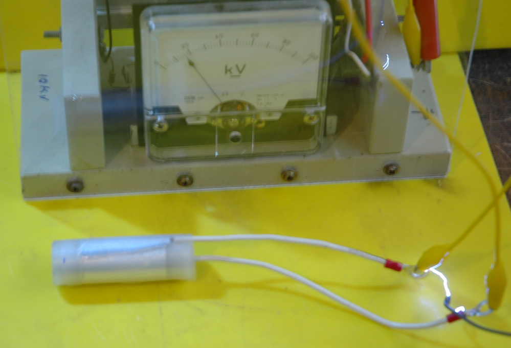
The upper photo shows the spiral line generator operating like a Blumlein generator making 30 kV from 6 kV. This high voltage at the ends of a roll results in a high voltage and is one reason why my rolled caps failed. The other being voltage stress which can be helped by using multiple small segments.
So I went on to make a prototype (1/10 size approx). I found a good way to join wire to aluminum foil and I had 4 segments wound continuously on one roll, so that any currents would inductively oppose and cancel.


The photos above shows the construction of 4 capacitors in series. The electrodes come from opposite ends to avoid the Blumlein voltage increase and the net current vectors should all cancel giving a low net inductance. There are two main foils which join to the electrodes and 3 intermediary foils to divide the voltage stress giving 4 capacitors in series. The electrodes were solid, capacitance was around expected at 273 pF. It stood off 20 kV easily and stores it for a while. It was looking good. So on to the working model.


 The photos above show the construction of the electrode attachment with an aluminium foil loop for each small bunch of copper wire strands. The final result around predicted was 26.8 nF. It’s a big cap at 2 feet long and I did not intend to put it under oil.
I felt good about this. Smart design for low voltage stress and low inductance. Hooked it up to my 4 inch coil, puffed out my chest and tried to tune for a spark….any spark. There was nothing, nada, nix. I replaced it with a good cap which gave 3 foot sparks to confirm everything else was OK.
I was completely puzzled. I even unrolled the cap to exclude a short, checked static DC capability and capacitance and all were OK. I tried to check the caps self resonant frequency to get a handle on the inductance but seemed to get equivocal results.
I am still not sure where my design has failed. Presumably the inductance is high and isn’t cancelling. I did rewind this on a larger former to have less difference between inner and outer radii but to no avail. There were 30 turns in the original, but I am having trouble getting my head around what is going on. Any ideas?
Related pages
Try something else
External links
Photo Date: June 8, 2008