Magnetic field lines can be made visible
Iron filings, magnetic viewing film or ferrofluid can all make magnetic field lines visible. Isolated readings can be also taken with gauss meters. Sure there are some nice computer graphics of predicted fields and the earth’s fields. But what about around other places such as large irregular magnets or even the earth’s magnetic field lines in your back yard for example?
“Continue reading” for more effects photos, the electronics, program and links…
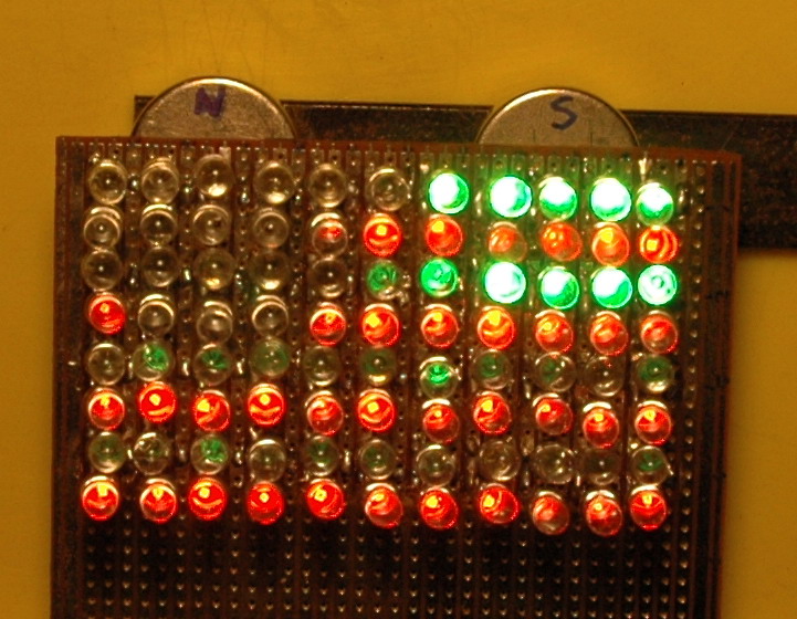
I have previously done a magnetic sensor array which outlines magnetic field lines. However, this is relatively insensitive and inflexible.
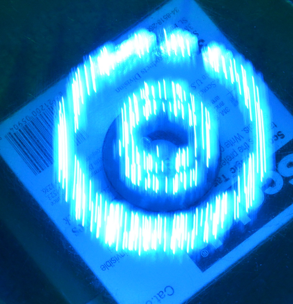
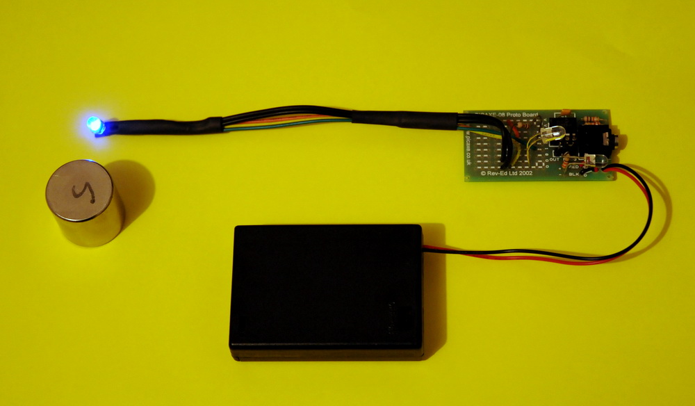
The photo above is taken by a (discontinued) UGN3503 Hall effect sensor being waved over a magnet. This on its own can sense the magnetic field strength that it is passed through. What I have done is to take this reading and feed it back to a LED just on top of the sensor to give real time and space readings.
Of course, we are used to looking at the whole field, so a long exposure photo needs to be taken to show multiple readings.
The field around the NIB magnet above is a cross section through one end. To take this I wave the sensor and LED over the magnet for 30 seconds while the camera is exposing. Still fairly coarse. I need a smaller LED. There is lag when changing direction due to the time the code takes to run.
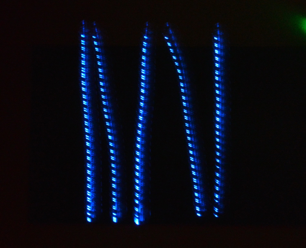
This is a few slow passes across a magnetic fridge sign with the characteristic long narrow magnetic field lines. This is a lot sharper.
The PIC microprocessor
The smarts are provided by a PICAXE microprocessor which repeatedly reads the Hall sensor. At a pre-defined magnetic field strength the LED will be switched on. With a 4 MHz chip it is just sufficient for reading one sensor.
PICAXE-08 code
; Magnetic field lines display
; Peter Terren 11/5/13
; UGN503 Hall device runs at 4.5V. Ratiometric. Zero field 128 varies from about 50 to 200
; This goes to ADC 1 to be read into b0
; Output 2 to drive a LED (with serial 2.2k resistor) just above the sensor.
; The sensor/LED are waved in a magnetic field and a long exposure
; in the dark captures this as light on a dark background outlining
; fields lines of the selected magnetic intensities.
main:
readadc 1,b0 ; ADC on port 1 (pin 6)
if b0 < 50 then top
if b0 < 68 then bot
if b0 < 70 then top
if b0 < 88 then bot
if b0 < 90 then top
if b0 < 103 then bot
if b0 < 105 then top
if b0 < 115 then bot
if b0 < 117 then top
if b0 < 120 then bot
if b0 < 122 then top
if b0 < 125 then bot
if b0 < 126 then top
if b0 < 127 then bot
low 2 ; LED off. LED on port 2 (pin 5)
goto main
top:
high 2 ; LED on
goto main
bot:
low 2 ; LED off
goto main
debug b0 ; Put under main to get mag field level (slow). 128 = no field
I know it’s not tidy but good enough for a quick prototype. I am sure that there is a faster way.
I am setting up a larger PCAXE-20X2 with more ADC’s and outputs running at 4 times the speed. I will use the more modern A1302 Ratiometric Hall effect sensors which are also 1.3mV / gauss.
With these I can work on a 3 axis setup with a tricolour LED to outline the different magnetic field line directions. It should at least be colourful. If it works well I can extend this to an x-y plotter to give a tidier image.
Later, an earth’s magnetic field tri-axis meter would be interesting to plot the magnetic field lines around a car for example. These are available for the Arduino. Another programming language. Sigh…
Related pages
 Magnetic sensor array
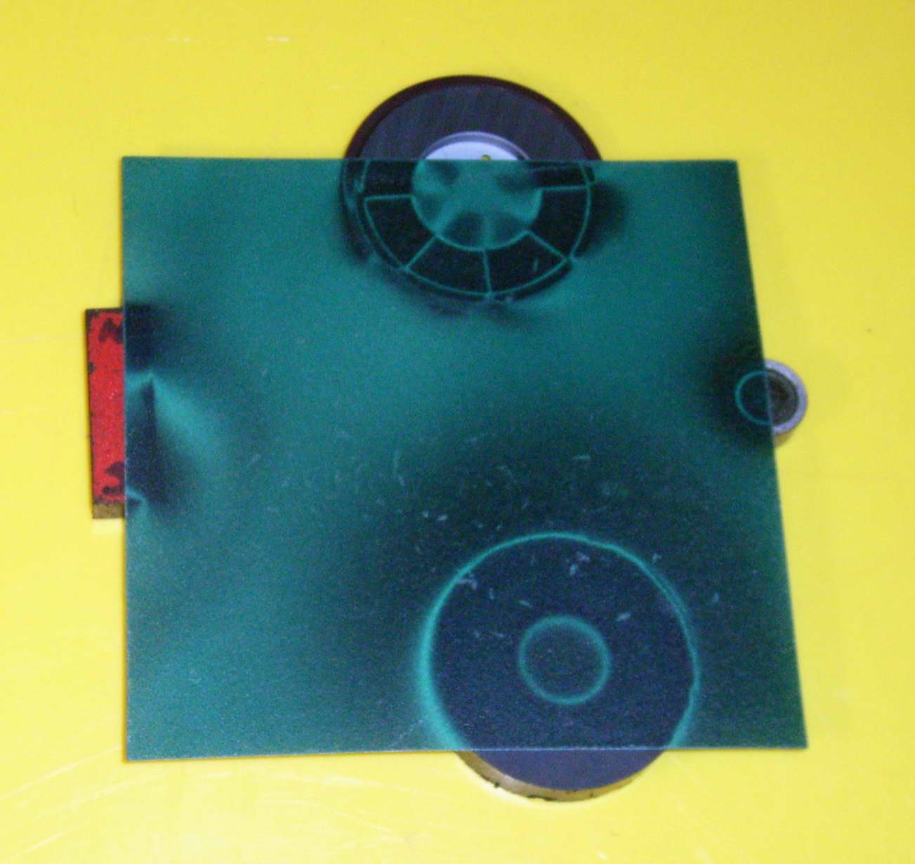 Magnetic viewing film
External links
Magnetic fields – Wikipedia
Hall effect sensors – Wikipedia
Try something else
 100 kV from a dental transformer
Photo Date: May 11, 2013
