Jacobs ladder
2003
A Jacob's ladder is an arc that forms between two upright electrodes that
are wider at the top. The arc starts at the bottom and rises with the heat
of the arc becoming progressively larger until it "breaks" at the top.
It then reignites at the bottom to start over again.


 (click to enlarge)
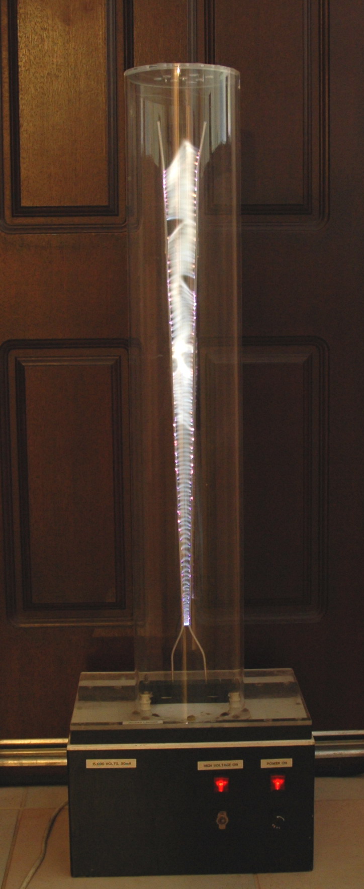
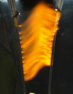
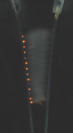
The left photo above shows the Jacob's ladder powered by my original old unpotted NST and shielded with acrylic
tube to allow safe public display.
This was struck by my TC resulting in
mains arc-over in the power switch and fuse and also destruction of the
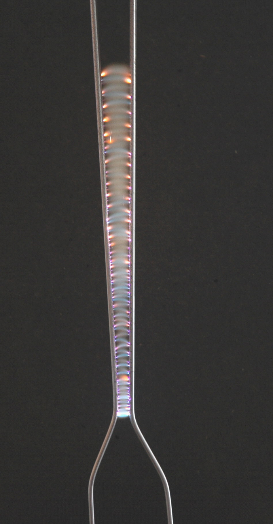
limiting resistors for the indicator neon's. I need a bigger shed. The centre photo
shows a 1.6 second exposure showing the arc rising in steps.
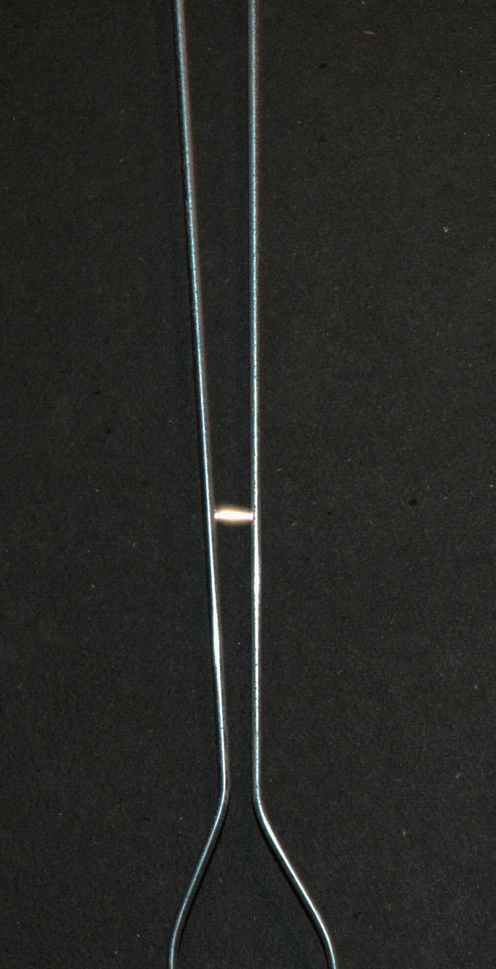
Occasionally there is orange in the spark due to sodium (from salt in sweaty
hands on the electrodes). The right photo shows the arc as it
rises in a 0.016 second exposure (1/60 sec).
Jacobs ladder from microwave oven
2008
 (click to enlarge)
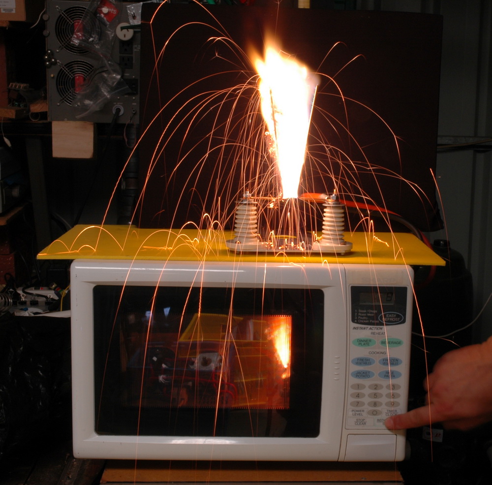
Above shows a Jacobs ladder running off a microwave oven
power supply. It has a voltage multiplier to allow starting voltages
of 10 kV and runs through a 10 K ohm 100 W ballast resistor with the MO set
to cook for 10 seconds. The shot also catches a poor contact arcing
internally and burning up the plastic wire coating inside the cooking space.
Jacobs ladder with water
electrode(s)
2005
 (click to enlarge)
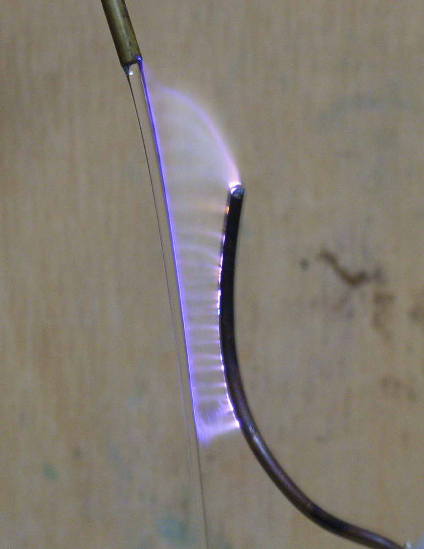
Above shows a one sided ladder using water from our salt water pool.
Simple gravity feed siphoning from a plastic tube into a metal nozzle with
6kV NST.
![]() (video 390 k - run mouse over)
(video 390 k - run mouse over)
Video above shows this in action.
 (click to enlarge)
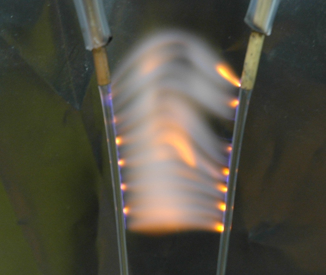
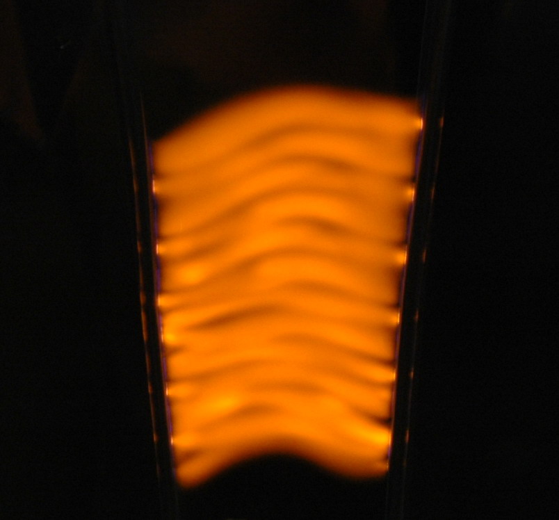
The left photo above shows the Jacob's ladder with dual water streams
using seawater powered by a 12 kV NST . Exposure is 1/8 second. See how the
sparks are orange with the salt on alternate half cycles. It is only
one electrode polarity that gives the color. The centre photo
shows a 0.4 second exposure showing the arc rising in steps and the plastic. The right photo
shows a 1 second exposure so the spark is only 1/8 as bright as in the first
photo.
 (click to enlarge)
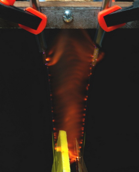
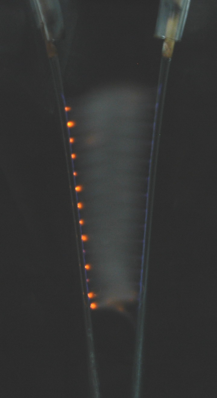
The left photo above shows the Jacob's ladder with dual water streams
using seawater. Sometimes if the spark lingers on a pool of salty
water it colors the flame much more strongly. The centre photo
shows a the spark with seawater in the left stream and copper sulfate
solution in the right. Note the loss of the sodium yellow color.
Right photo shows the intense color of the sodium in the ladder.
Circular Jacobs
ladder (and concentric circles) 2007
A conventional Jacobs ladder has a spark that moves up as heated air rises.
But one can also move a spark by the action of a magnetic field.
 (click to enlarge)
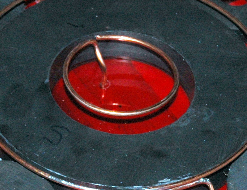
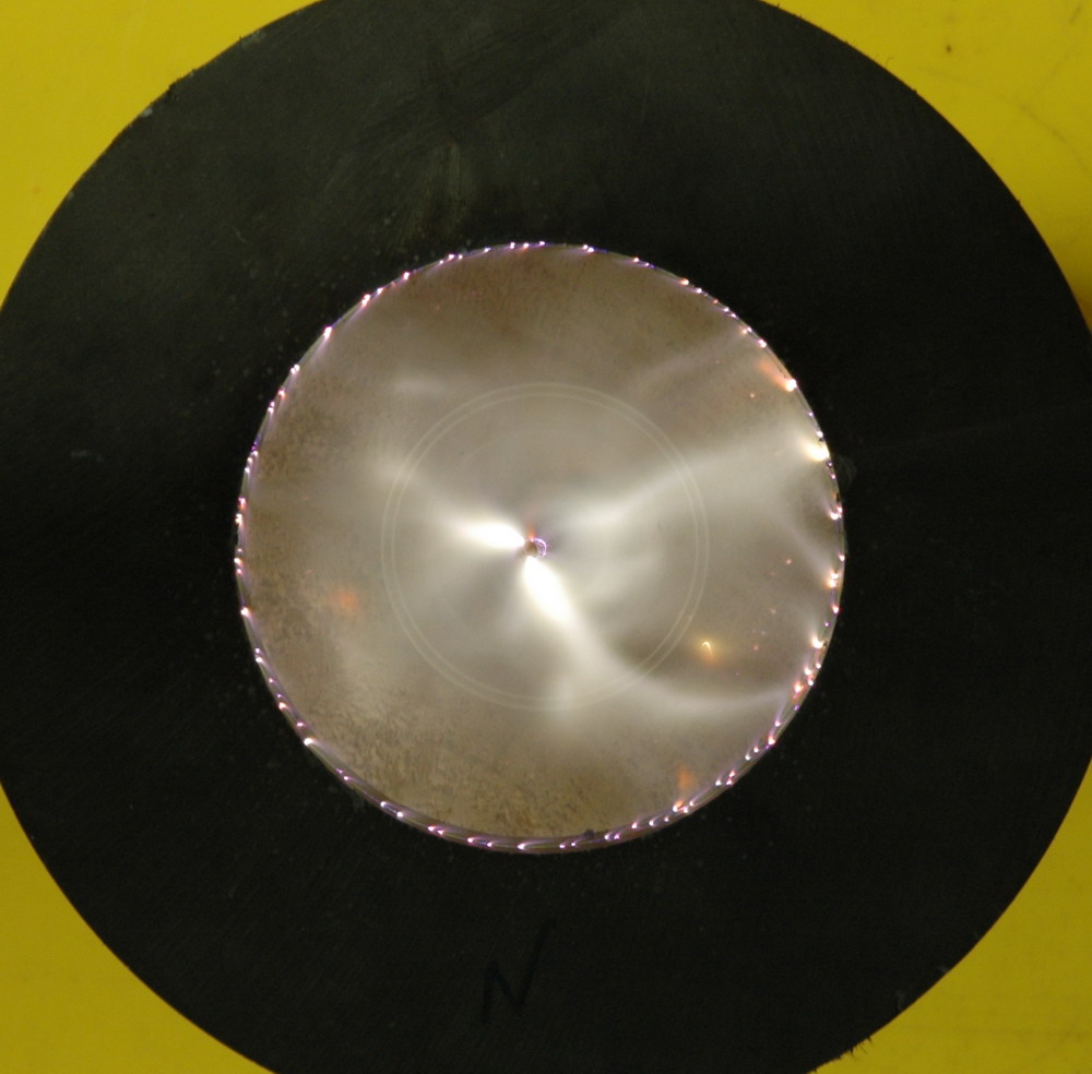
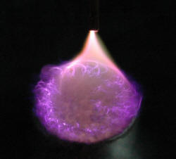
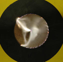
The photo above shows a spark to a NIB magnet (which is just under water).
The arc will race around in circles and blur into a conical flame. The
reason is the magnetic field resulting in a force on the current flow just
like the right (or is that left?) hand rule which is the basis for electric
motors.

 (click to enlarge)
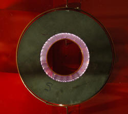
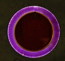
The left photo above shows a circular copper ring close to the inside
of a 15cm diameter toroidal ferrite magnet. This happens to be
conductive (many ferrites aren't). The S indicates the South pole is
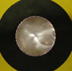
uppermost. The center photo shows the gap filled with a
rotating spark that does several rotations per second if the power is high
enough. The right photo shows a close up at lower power.
Now consider a ring on the outside of the magnet to create the same on the
outside. This is a little harder probably due to the direction of the
field lines. However by shaping them with some external magnets (circular
ferrite magnets from microwave oven magnetrons) a reasonable circular spark
can be obtained. This does tend to decrease the free running of the
central hole though.
 (click to enlarge)
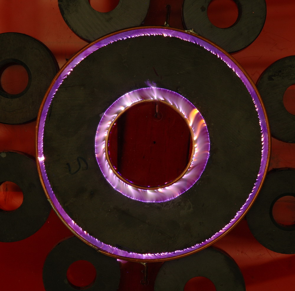
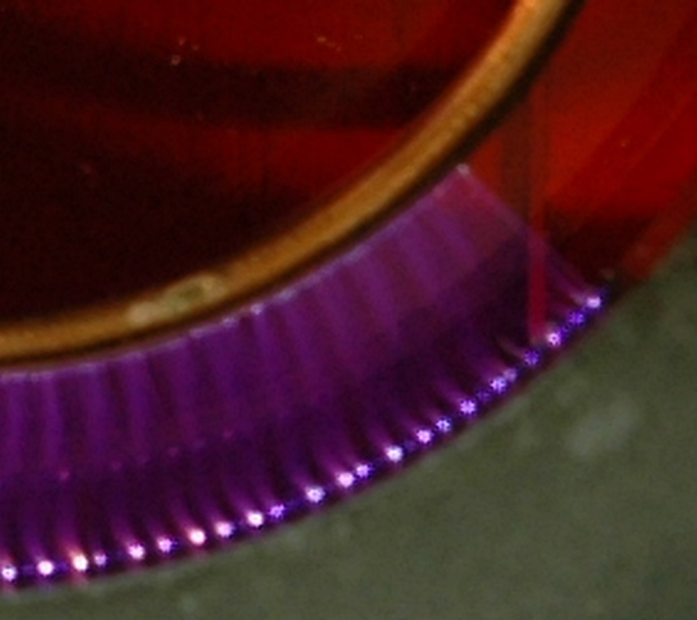
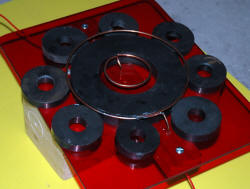
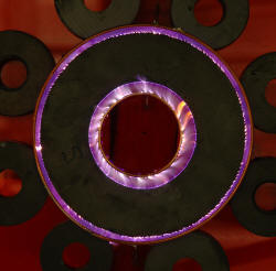
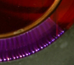
The left photo above shows the dual copper rings, large central
ferrite magnet and 8 smaller ferrites. The center photo shows
the dual concentric 'circular Jacobs ladders'. The right photo shows
detail.
 (click to enlarge)
The left photo above shows the effect of a single electrode in the
center. With enough voltage to jump 3.5 cm plus enough current to form
a continuous arc, it will spin around rapidly. The right photo shows
an exposure lasting a couple of rotations. These yellowish arcs are much
longer than the lower powered purple ones above.
Of course, if you have 3 kv at 500 A (1.5 MW) available then
Lorenz forces are greater than gravity and heating. See this
fearsome circular
Jacobs ladder.
A 500 kV hot disconnect
gives a massive 40 foot rising spark. No doubt a good amount of line
inductance helps.
Jacobs Bi-ladder
2007
This is a bidirectional Jacob's ladder and has sections that go both up AND
down. But how can that be?
 (click to enlarge)
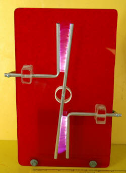
The photo above shows the Jacob's Bi-ladder. The long central rod can
rotate to widen the gap. It was run from my 80 kV DC supply.
So how is this done? The normal upper segment works by the usual
heated air mechanism. The lower segment is magnetically driven and has
the North poles of three 1 inch NIB magnets just behind the red acrylic
 (click to enlarge)
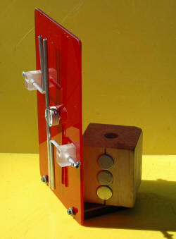
The photo above shows the concealed NIB magnets behind the red acrylic.
Left electrode is positive and North poles are closest.
However, after some thought I realize that there is another way to achieve
an identical photo without magnets. You need this setup in a box containing
the camera which are all free to be rotated so they are upside down.
If the ladder is rewired so the sparks are between the central electrode and
the uppermost outer electrode, then a long exposure with one rotation
through 180 degrees (switching to the upper electrode when it rotates), will
give a good result.
100kV DC
(dental x-ray unit)
2004
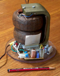
This is from a small x-ray transformer. This was given to me by a friend who got it for AUD$1 on eBay
(Thanks, Ralph). It is
from an old dental x-ray machine and is rated at 60 kV. It
looks tiny for a mains transformer to give this even under oil. It doesn't
have any shunts and can draw 15 A from 240 V. I connected
it up and with about half power (125 V) it puts out about 30 kV at 20 mA
before internal shorting occurs and the oil starts to bubble. Occasionally
it will run to a 2 1/2 inch spark on the full 240 V. It has a lot more
power than an NST.
 (video 570 k - run mouse over)
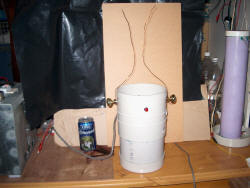
Above left is the 60 kV transformer with a bit of suppression circuitry (ex
microwave). The video shows the transformer under oil in a PVC pipe
running as a Jacob's ladder with a drink can next to it for scale.
A
Jacobs ladder is a spark gap in which a spark forms initially between the
lowest and closest points then rises as the plasma heated air rises.
It eventually extinguishes near the top then restarts at the bottom. A favourite
backdrop for old Frankenstein movies.
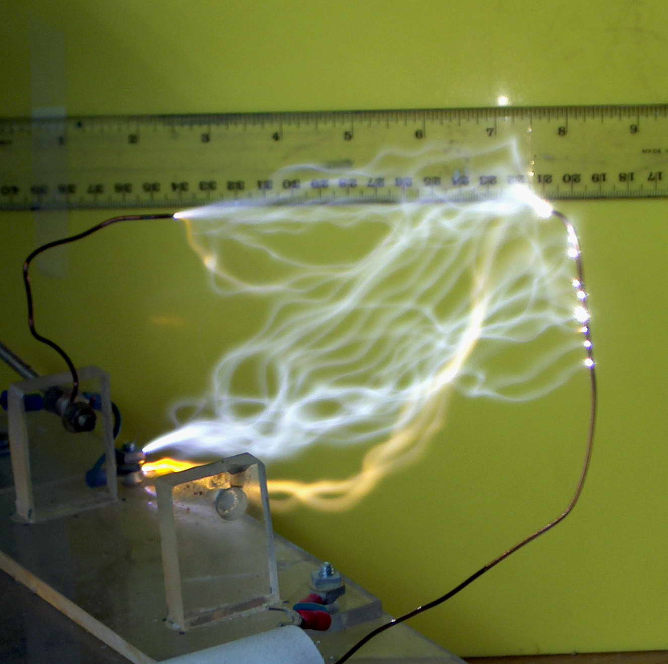
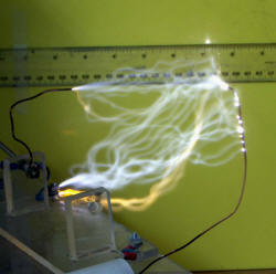
To obtain around 100 kV DC from this 60
kV x-ray transformer I input 150 V AC which gives 36 kV AC out. With a diode and a 0.015 uF 80 kV mica capacitor connected as a voltage doubler, around 100 kV DC is achieved giving a best spark of
5 inches
(13 cm). Note the spark is hazy (and fairly quiet) due to
current limiting with a resistor and an inductor to reduce strain on the
capacitor. The whole setup crackles with corona when in action.
 (click
to enlarge)
(click
to enlarge)
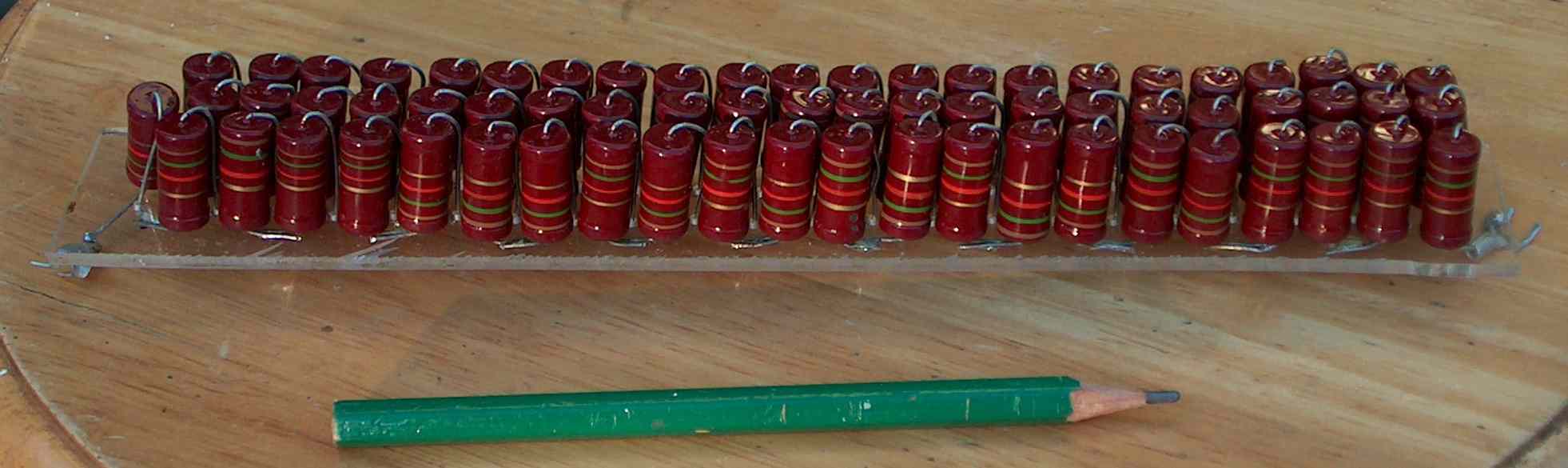
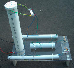
The spark above is attenuated with a resistor (below right and the short
central poly tube in the left photo) which has 67 x 1.8 k
ohm resistors and is almost exactly 100 k ohm. The voltage rating is
unknown but for these 2 or 3 watt types is probably around 1 kV each. It was
placed in a PVC pipe and filled with paraffin wax. I have had these in
my junk box for around 20 years so I hope they aren't past their use-by
date.
 (click
to enlarge)
(click
to enlarge)
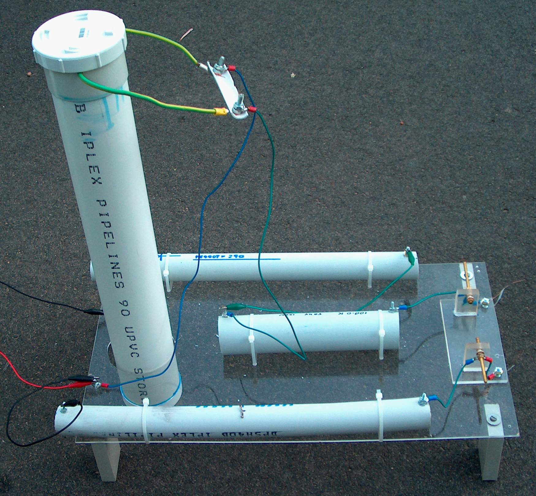
The capacitor (the upright tube in the photo) is a 2.2 nF rolled polyethylene in oil cap composed of 2
sections with 8 layers of sheet in each side. I have a 1 3/4 inch (4 cm) safety gap which only starts to fire
at output sparks with the voltage doubler of 4 inches (10 cm). This was
replaced with the mica caps for the highest voltages.
 (click
to enlarge)
(click
to enlarge)
The diode is composed of 290 x 1N4007's in a PVC pipe about 15 inches (40
cm) long. Each one is rated at 1000 PIV at 1 A. This was designed to
accommodate the full 60 kV AC = 169 kV peak to peak. Allowing for 10%
increased voltage from the variac gives a total 186 kV which allows 50%
headroom only. Note no dropping resistors were used. So far no
problems (but many lesser ones have come to grief). I now have two of these
to allow another stage to my voltage multiplier.
I also have an inductor made from 21 g wire close wound 15 inches on a 1 inch (2.5cm)
former. The inductor and resistor are needed to limit the
current for devices such as the lifter (below).