
|
|
|
                                   
 |
Low voltage (but high current) 2004
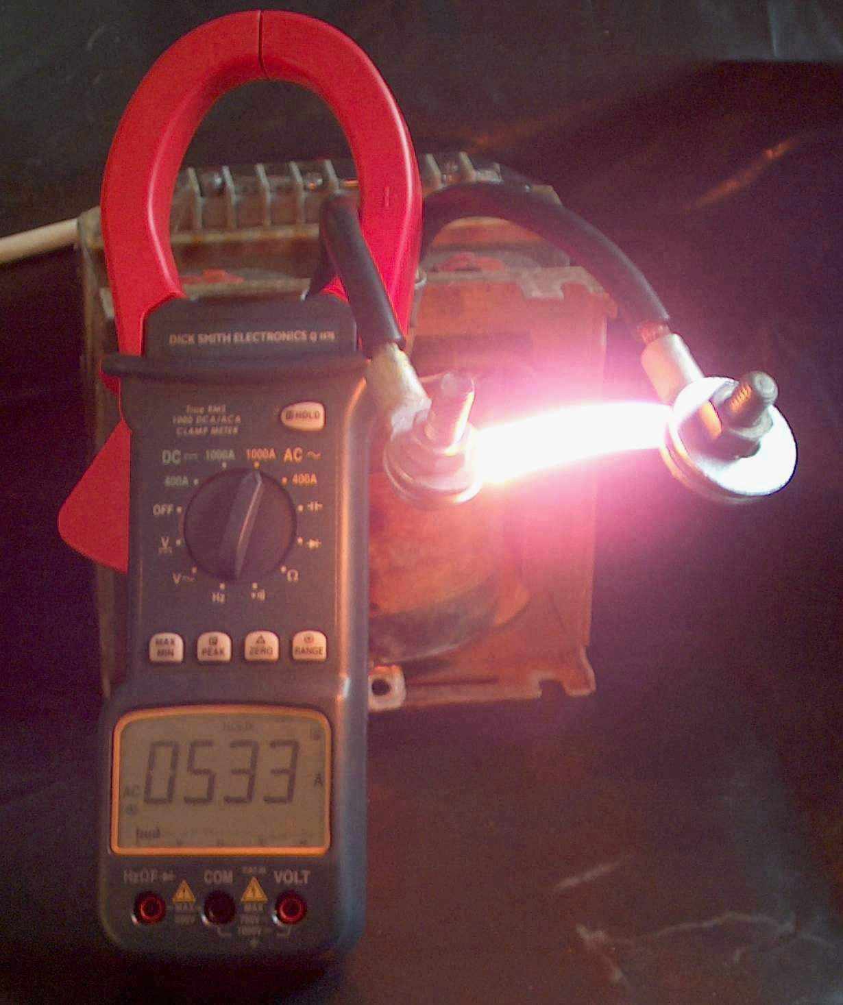
Check out the 533 A current on the clamp meter from this transformer (above). The secondary is wound with 12 mm by 3 mm rectangular wire and is rated at 6 V 90 A. Seen here heating an iron strip from a transformer lamination with about 1.1 volts across the two bolts = 600 W. At this current it will melt if left on for more than a few seconds for the picture. Short circuit current is around 830 A plus. This was another of my junkyard cheapo transformers for around AUD$20.
Spotwelder 2005
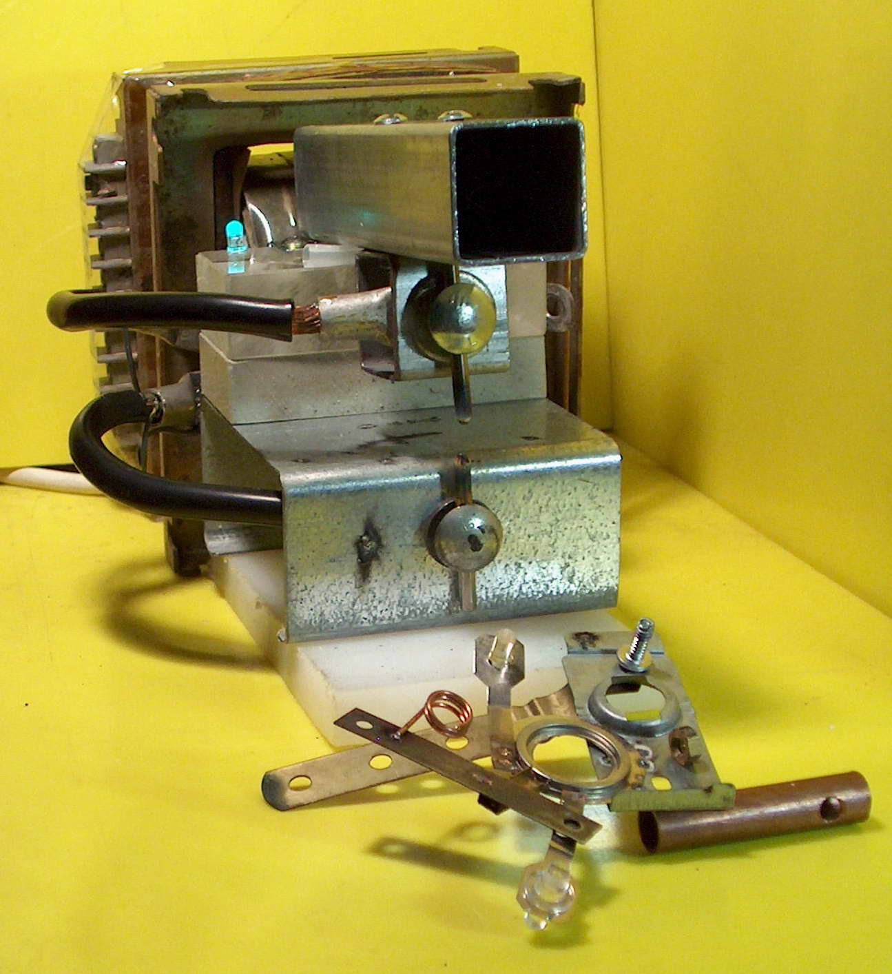
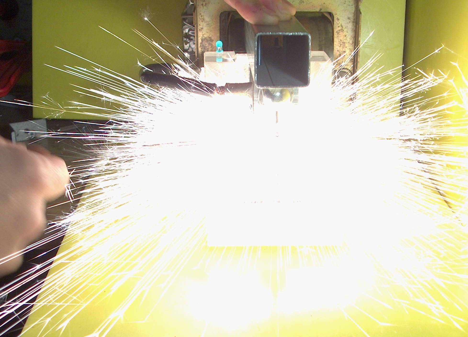
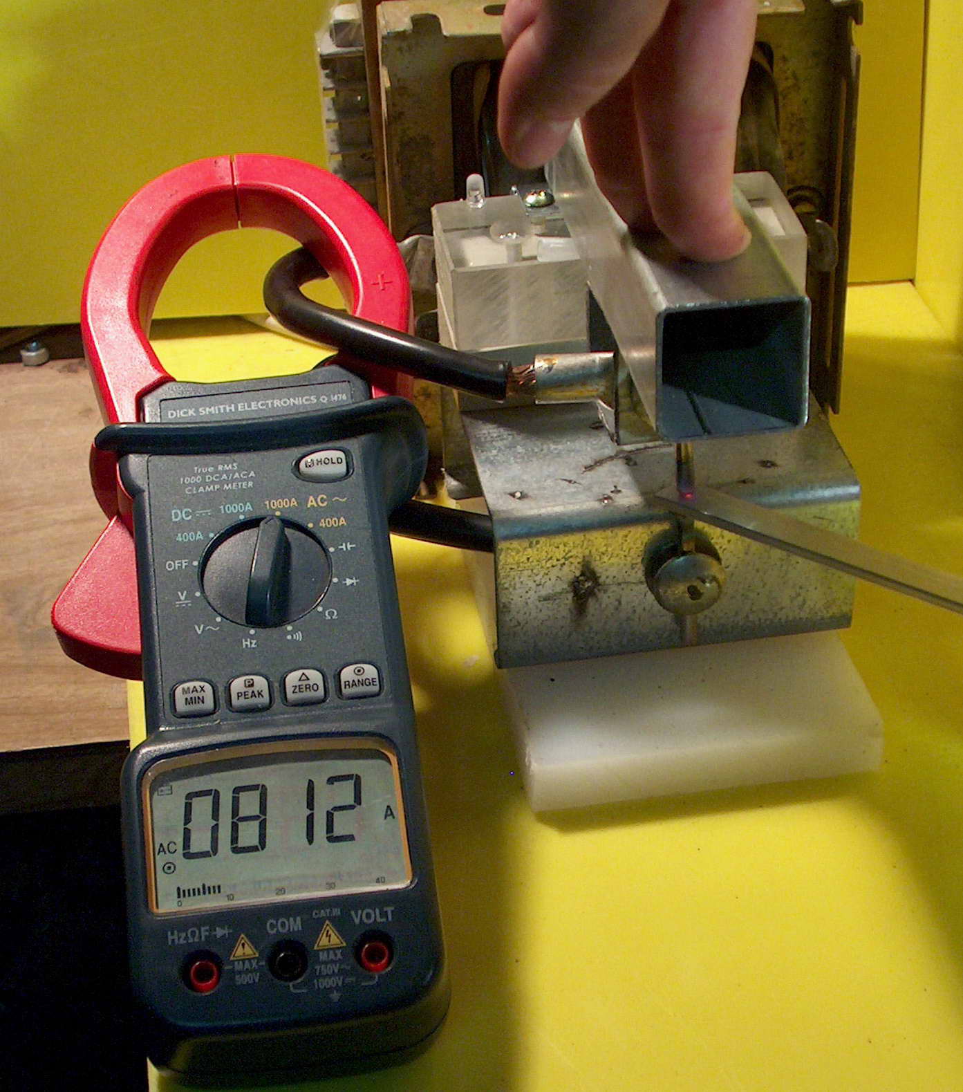
The left photo shows the hinged arm which allows two tungsten electrodes to come together. I also shows various bits of metal joined with this (very 'art nouveau'). The middle photo shows the flash if there is a poor contact. The right photo shows a good contact and 812 amps flowing. About 1-2 seconds later the tungsten rod was red hot. The 8 mm black cables get hot even with a few shots.
Marinov Motor
2005
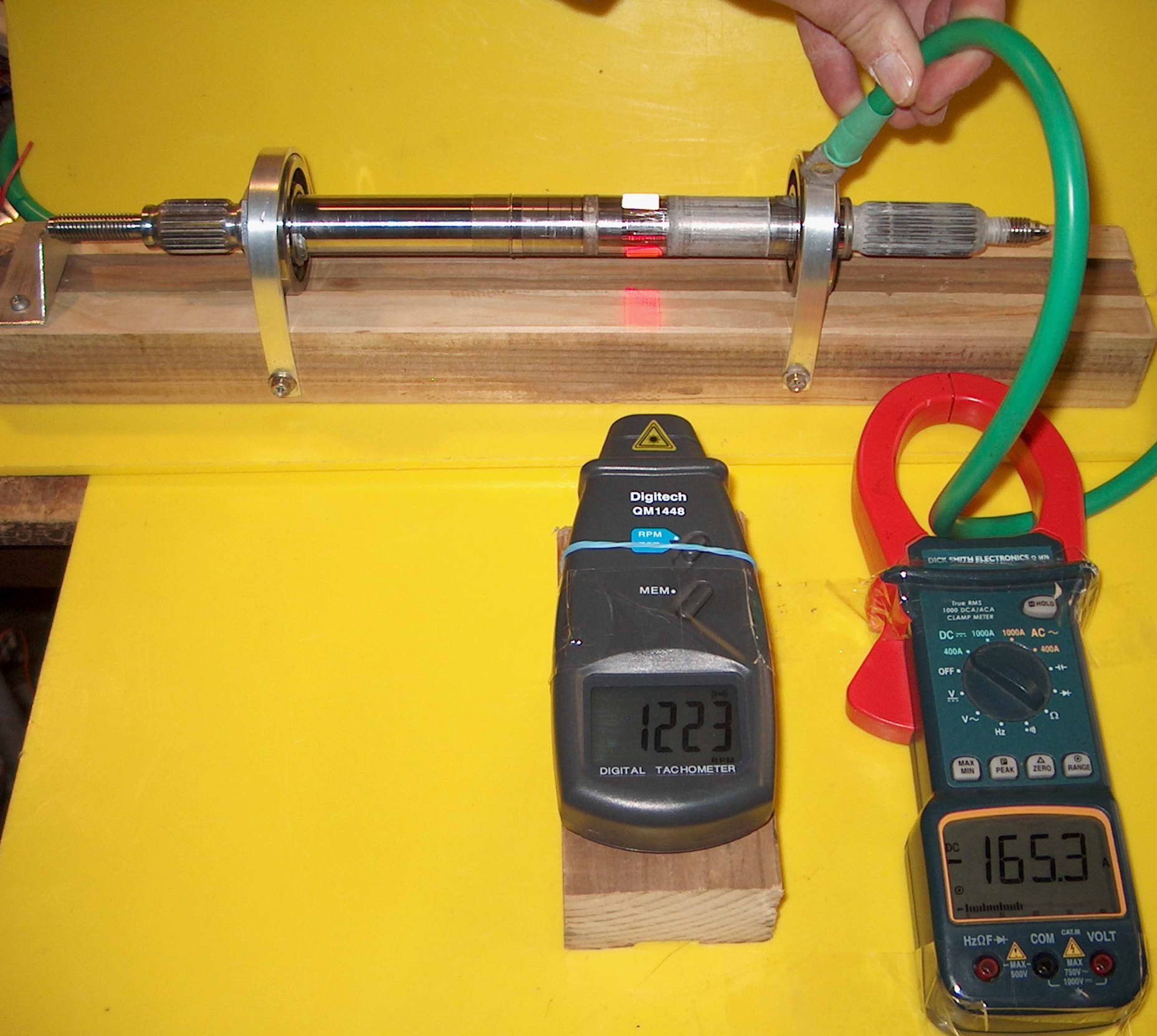
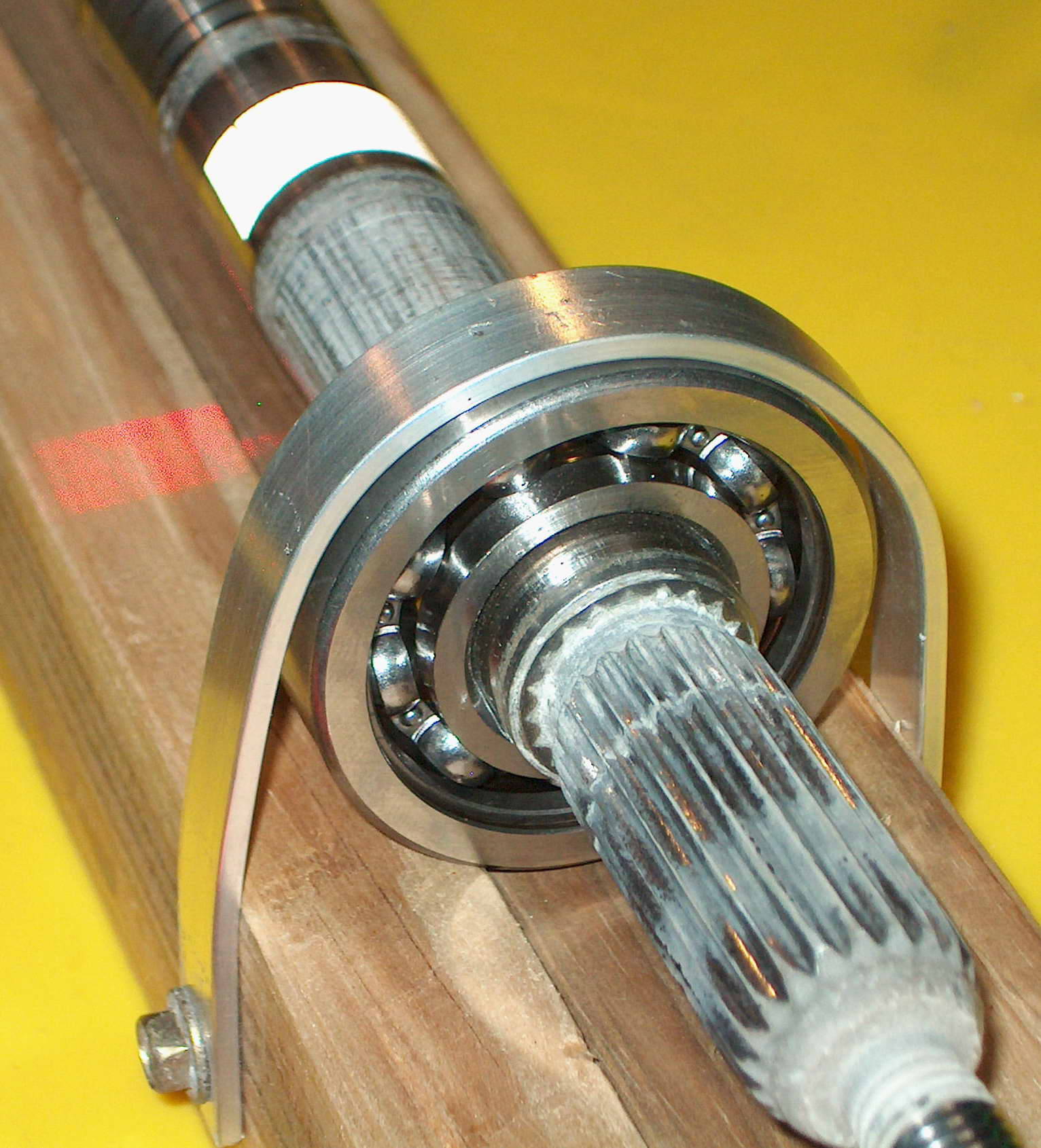
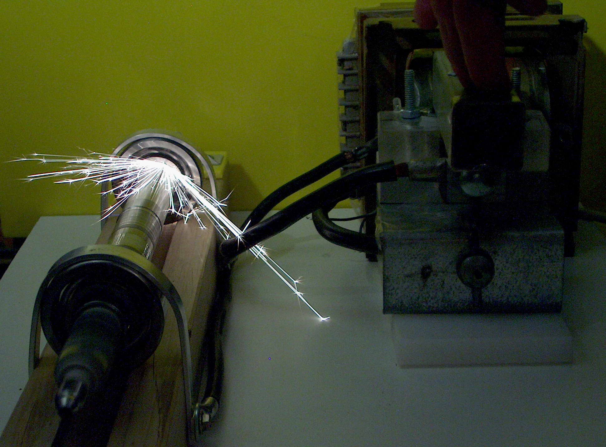
The left photo shows it running at 1223 RPM at 165 A but the flash has stopped the motion. The centre photo is a close up of the bearing. The right photo shows it running at higher power on AC this time from my 6 V 90 A transformer ($20 junkyard find) which I have added to my spotwelder setup which happens to work fine as a high current switch. With the AC the current is 365 A and peak RPM 2016 before thing start sparking, overheating and slowing after only 5 or 10 seconds. Even the heavy black cables 6 and 8 mm get warm.
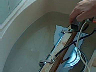
This is a video showing the motor running underwater (1Meg). It runs slower as expected but still runs. You can see the tungsten switch electrodes glowing red as well.
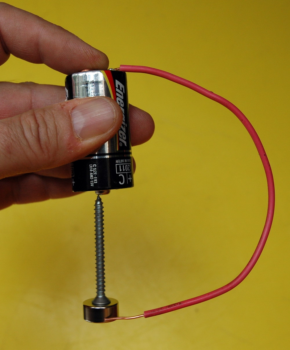
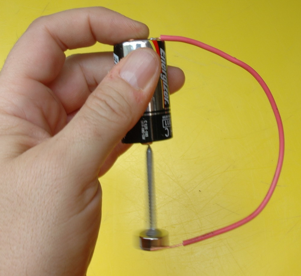
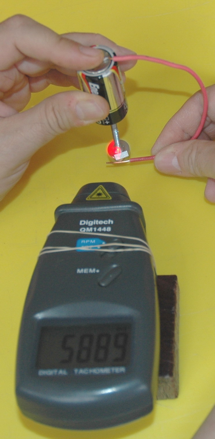
Homopolar motor
2006
The left photo shows the components of a screw, battery, wire and NIB magnet. The middle photo shows it running. The right photo shows the impressive 5889 RPM.
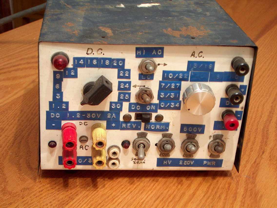
My sentimental favourite power supply was made in 1971 and was developed over the years. It appeared in the local newspapers 8 times as a backdrop to photos about two of four state wide talent quest prizes I won between 1970 and 1973. Currently (no pun intended) it is defunct but previously supplied 1-30 V DC at 1 A with a LM317 regulator, and a range of AC voltages from 3 V to 500 V.
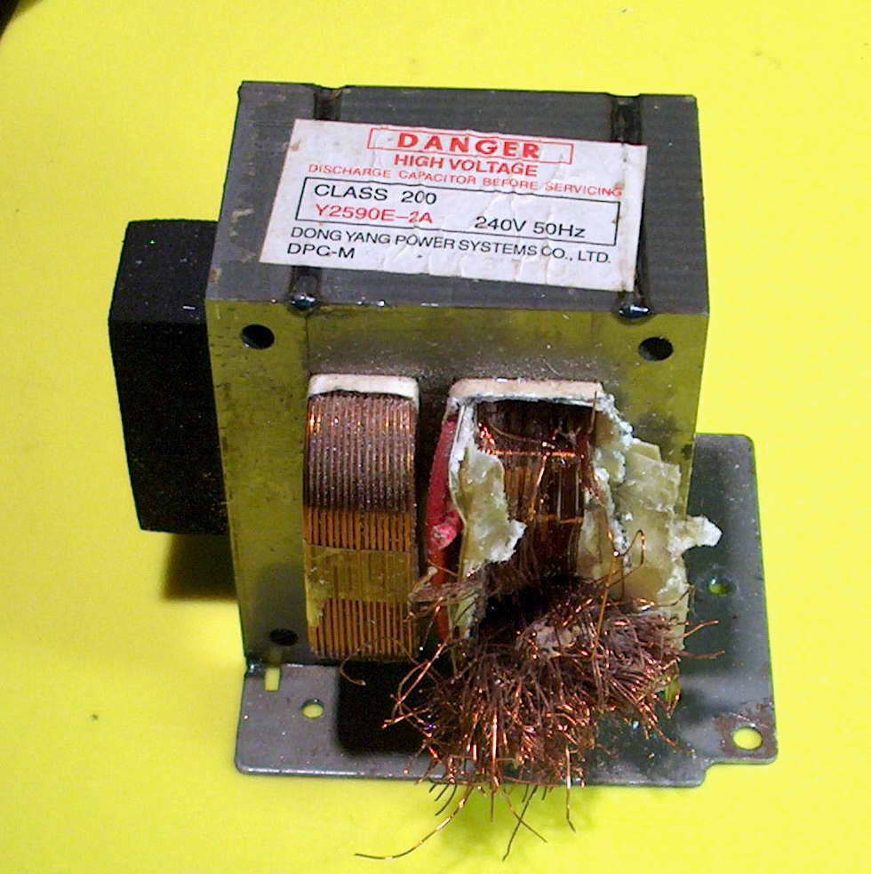
Low voltage supply using a MO 2005
Left photo shows removing the HV windings the hard way. Usually easiest to hacksaw off the winding flush then use a block of wood and hammer them out. Can't be done easily with this vertical winding style however. Middle photo shows the 0.83 volts AC (RMS) for a single turn at the rated 240 V AC input. Right photo shows 13 turns being one side of a centre-tapped winding. This gives 11.8 V AC which will be 23.6 V AC which after the diode bridge rectifier will be 23.6 * (sqrt 2) = 33.6 volts. This will be reduced by the voltage drop of the rectifier to about 32 V DC peak.
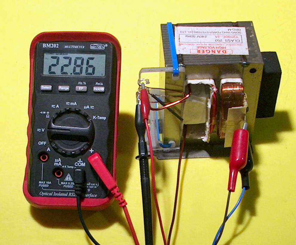
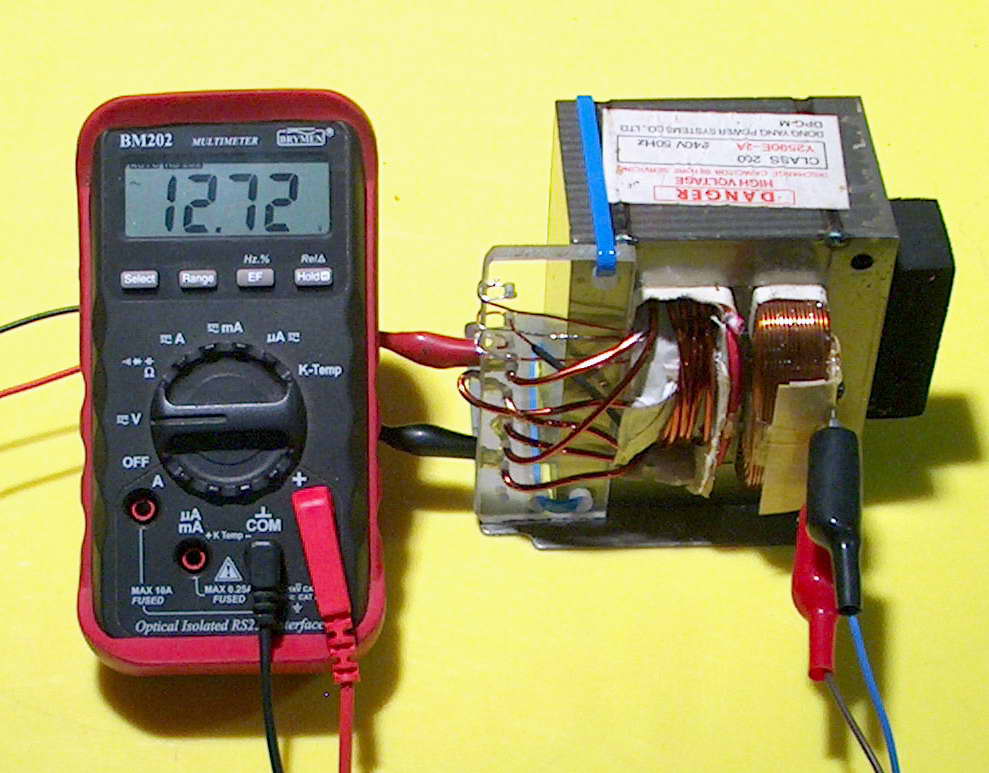
Left photo shows the full 26 turns centre-tapped giving 22.86 V which is a little different to the 23.6 above due to slightly different input voltage. Right photo shows the addition of heavy gauge windings of 4 + 4 + 7 windings in series to give 12.72 V AC. This allows the many AC voltage combinations from 3.3 V to 35 V. Arranging selection of these is now the consideration, along with a range of DC voltages at an appropriate cost i.e. nearly zero.
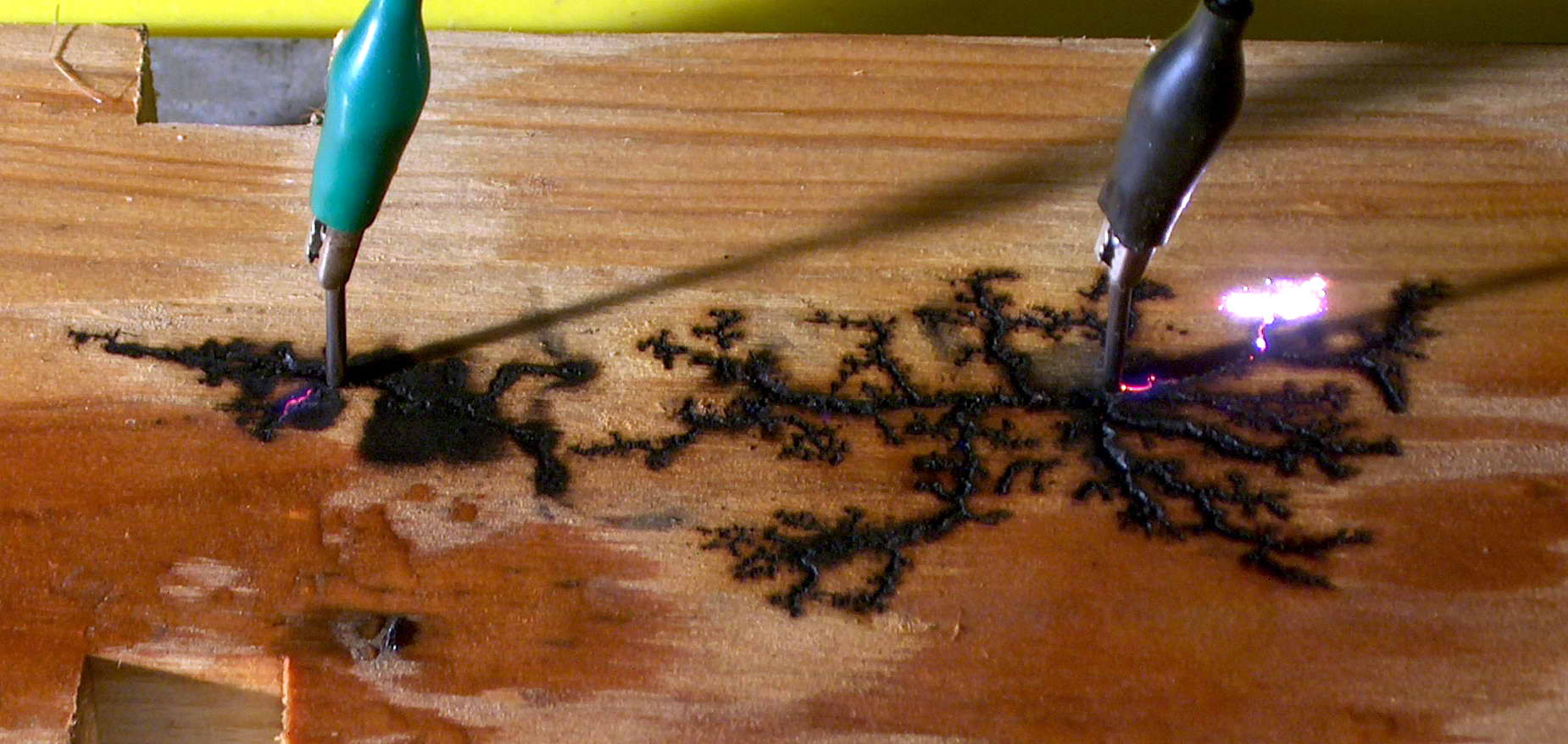
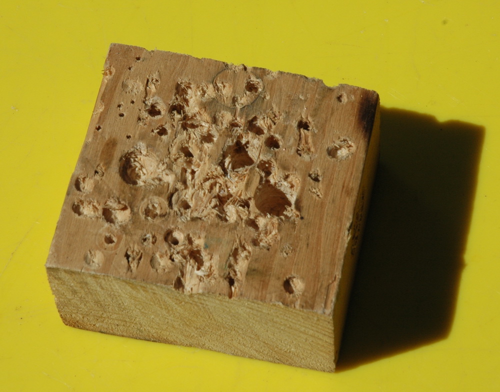
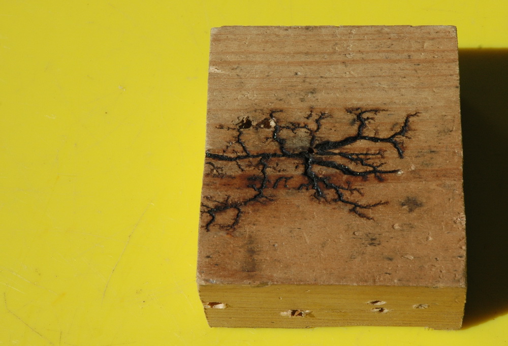
Here is what happens when you put a few kV between two nails in some wet pine. I have adjusted the voltage between 2 to 10 kV from my single MOT with voltage multiplier as used in my laser supply altering it periodically to promote the spark or prevent flames. If things stopped I added a water spray. They burns have a curiously fractal nature about them. Note that the burns are just as likely to burn away from the nails as towards. I didn't encourage things either way. Now fast forward 4 years to 2008. That block of wood got thrown back into the "miscellaneous lumps of wood" box, was cut in half and drilled extensively on one side. I could never bring myself to drill in the fractal side.
The original woodburn fractal block after 4 years of misuse. So why the concern now? Well it has been put on Wikipedia as a fractal example. The photo description and detail is here on Wiki.
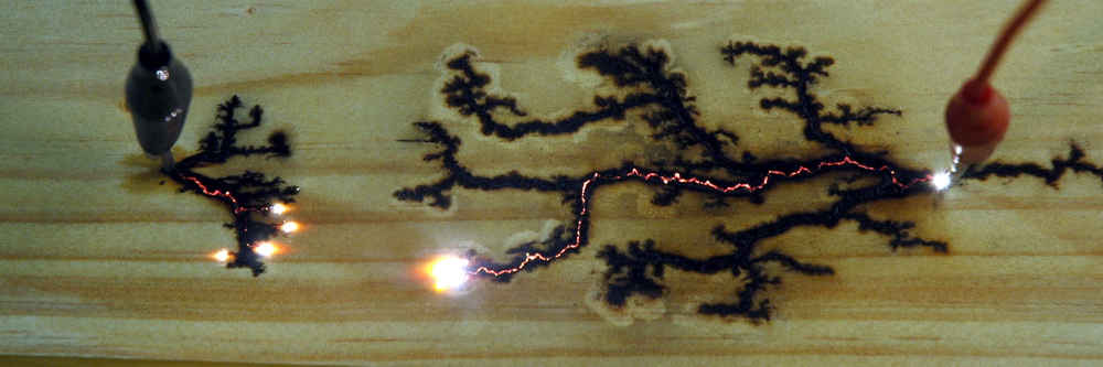
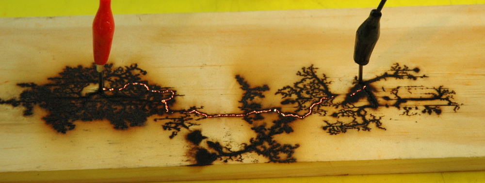
Above shows some more examples done in 2008 using pine done at perhaps 4-8 kV. I like the burning red line between the nails. Easily seen on the enlargement. The power supply was a 13kV MOT supply current limited with a 100 kOhm resistor. Any current limited supply could be used though, like a neon sign transformer. A variac is helpful but you could probably turn the supply on an off to regulate it. It needs to be periodically sprayed with water - tap water or slightly salted, not deionised. Balsa wood seems much more conductive and only needed about 1500 V. I have done a video of this.
Big SCR's
2005
Above is my SCR clamped with two heavy copper busbars with insulated bolts
and is shown short circuiting a car battery at 210 A. I have to use the
quick release locking pliers as there is no switch here and once the SCR
goes on it stays on.
Here are pictures of my SCR autopsy. The ceramic is ungrindable and
unhacksawable (are these words?), so it came down to gentle caresses with a
ball pein hammer and cold chisel. in the last picture I am holding the
silicon disc with bonded metal on either side. |
||||||||||||||||||
This page was last updated June 03, 2009


