
Laser
galvanometers 2D 2006
I arranged two mirror galvanometers to give two dimensional control
of a laser beam. These have a response to about 100Hz but can still be used
to about 200Hz. I fed one with 50Hz and the other from a frequency
generator. This gives smoothly rotating complex patterns that vary with the
ratios of the two frequencies.
So 50Hz + 50Hz gives a circle, 50 + 100Hz gives a figure 8 etc.
 (click to enlarge)
These
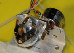
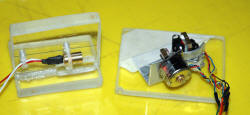
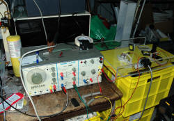
pictures above show the setup. The left photo shows a close up of the
two galvanometers mounted with rotational axes at right angles. The
center photo shows the setup with the diode laser. The right photo
shows my (sort of) optical bench to simplify beam paths and to allow
connection to the power supply.
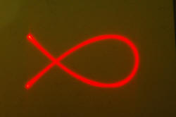
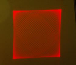
(click to enlarge)
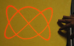
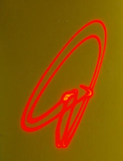
The pictures
above show some of the many patterns produced. These are constantly moving
due to the varying phase relationships and only "slow down" near an exact
ratio.
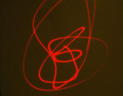
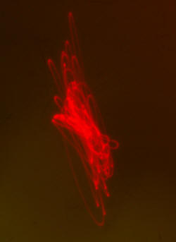
(click to enlarge)
The
galvanometers can be connected to the output of a stereo amplifier with
resulting scribbly patterns in time with the music.
 (click to enlarge)
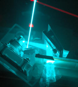
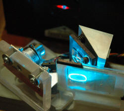
The
galvanometers setup for the argon laser. The beam passes to the two
galvanometer mirrors on to a mirror (first surface) and then out through a
diffraction grating (15000 lines per inch). This is only of interest
with the argon laser as it is a multi-line laser with about 5 colors in one.
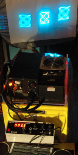
 (click to enlarge)
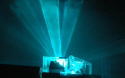
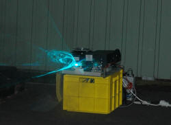
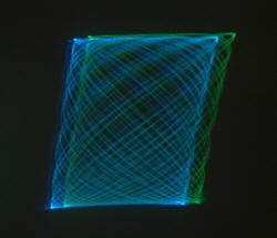
The
argon laser setup indoors with the split beams and outdoors with some smoke.
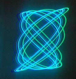
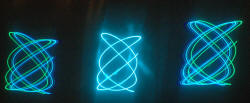
 (click to enlarge)
The digital
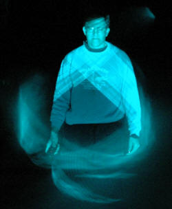
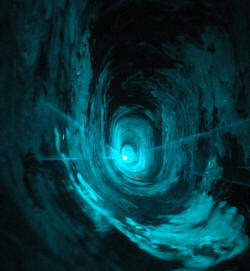
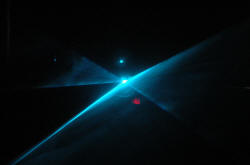
camera doesn't do justice to the violet and deep blue colors.
 (click to enlarge)
"Beam me up,
Scotty" to far away galaxies... There are really dramatic effects by
making a smoke tunnel with a circular beam when you are inside it.
Particularly as it starts to close up on you.

Laser
Galvanometer 1D 2006
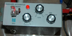
This is an earlier setup made from a discarded pen recorder from dumpster
diving at the Physics Dept.
 (click to enlarge)
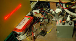
The left
photo shows the pen recorder unit. This would normally drive a pen on a
moving roll of paper (like a seismograph). It is 1981 vintage and has
offset, gain and calibration controls. Full scale deflection seems to be
about 0.1V and frequency response seems to go up to about 70Hz. Sadly, I
didn't pick up the second one. The right photo shows the beam
from a 5mW red diode laser reflected by a mirror. The unit is fed from
my frequency generator at about 70Hz and the result is a horizontal stripe.
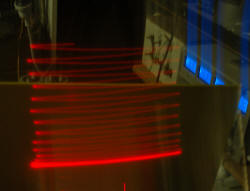
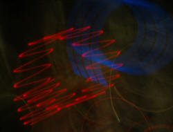

The circular
motion is simply me rotating the camera by hand with a 1 second exposure.
This brings out the sine wave signal.

Laser Scanner 2006
This is a motor driven hexagonal mirror the will spread a beam in the
horizontal direction. Presumably from a laser printer. I made it
up into a neat unit with a 5mW green laser. The laser needed 3 V and I made
a LM317 regulator to run at 3V for it.
I took the initial shots then found the laser and regulator were overheating
so I added a fan. I then blew the electronics of the mirror drive with an
accidental reverse polarity.
So now the tidy unit has a fan and a belt drive motor hanging off it - but
it works.
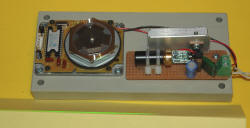
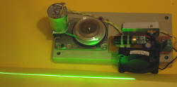 (click to enlarge)
The left photo shows the scanning unit and green laser. The right photo
shows the addition of the fan and the replacement of the electronic motor
with a crude belt drive.
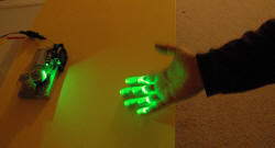
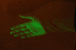
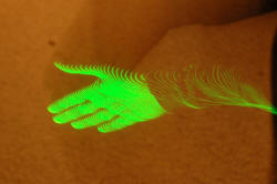
(click to enlarge)
The left photo shows my hand in front of the scanner. The
center and right photos
shows my hand moving through the scanner then out of the photo for the
remainder of the 1 second exposure. Note how you can see through the
hand.
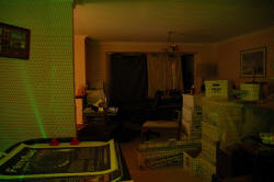
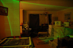 (click to enlarge)
These photos show a scans made by moving the scanner by hand, through a left
to right then up and down sweep in a room.

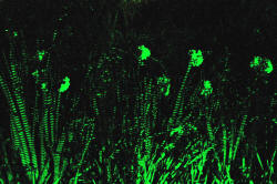 (click to enlarge)
A scan of a flower bed with identical frame.

Future Laser plans

