
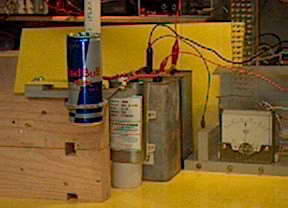
Can Crusher 2 reaches a power able to tear the can in half. This one uses a third high voltage 500 joule medical defibrillation capacitor. This makes a total of 1500 joules and with straight and shortened wiring paths this model performs much better.
“Continue reading” for more details and photos.


 The can before and after. Note the distorted windings where a short circuit has occurred and vaporized some of the wire. One wonders how many turns there were effectively.
 Video of the can being torn in half (720 k but worth the download for the few frames with action. Sound is good too). Watch the voltmeter too.
 There is noticeable crushing at 200 J, better at 300 J and the can tears apart at 1500 J. Also dependent on the turns used. Note that 3 turns at 2400 V 110 uF (300 J) had an effect but 3 turns at 5200 V 35 uF (300 J) had no effect. So experimentation is called for.
Enlarge the picture and you can see the “5% crushed lemons” and “low joule” labelling!
The top picture in this post shows the smaller Red Bull cans crushed at various energies and the effect of crushing a full can. The full can is interesting and bears further analysis. My interpretation is that the thermal and mechanical effects are on such a rapid timeframe that there is no conducting away of heat but the fluid has inertia and incompressibility. This has the effect of preventing the aluminium from folding in to the centre. It remains in the area of highest field which is right in contact with the coils. Hence, can disruption into the two halves is enhanced and since there is no infolding the “cut” is cleaner. Note that the energies on the photo are incorrect and should be 200J, 300J, 1500J and 1500J.
The fluid in the can undergoes a major drop in pressure as the two halves of the can start to separate. Hence the observation above that the upper part of the can is folded in. It is sucked in by low pressure rather than by the induced field.
This process is symmetrical and the net result is that the fluid forms a central column that stretches and becomes fountain shaped as in the video.
Video (700 k) shows effect of crushing a full can. The can rapidly disappears leaving a long stream of fluid. Look at it frame by frame if you can.
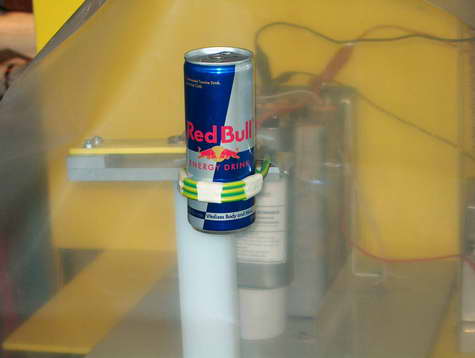
 The white stick that I am holding will be used to trigger the switch

 Some frame grabs at 1/30 second from a video sequence on tearing apart a full can. A messy business.
 This shows the results of attempting to crush a frozen can. Although it can’t crush the can does separate with a fine almost laser like crack with separation of the adjacent paintwork.
 This graph shows the effect on capacitor life expectancy of voltage reversal. If you have a capacitor rated for a given life at 80 % reversal (top curve) then it will last 40 times as long if the reversal is reduced to 10 %. Avoiding this can be done in several ways.
Firstly, with critical damping. I can reduce my reversal from 75 % to 25 % if I use 10 turns (instead of 3) but the rate of current rise is too slow for efficient crushing.
Secondly, by exploding the wire before the reversal such as Bert Hickman does with his coinshrinking.
Thirdly, by using a diode to catch the reversed voltage as I do in my electrolytic capacitor bank. This needs diodes capable of passing a current of perhaps 30 kA rapidly and blocking 6000 V. Not an easy ask. I have experimented with hockey puck SCR’s being used as a diode and this seems promising.
 Above: The voltage reversal on 10 turns of unloaded coil with the can crusher caps charged to only 30 V (rated 5000 V). Time base is 20 us/div and 5 V/div. This is without the SCR and shows 80 % or more voltage reversal (bad).
  Above: The SCR acting as a diode and reducing voltage reversal from 80 % down to 15 % despite the high speeds involved. A good thing and will potentially prolong the life of the caps by 40 times or so).
 Above: The stack of 4 SCR’s with high speed gate diodes and voltage dividers.
  The circuit diagram of the stack.
As I have 12 hockey puck SCR’s that I found in the dirt in a junk yard (amazingly) this is the biggest acreage of silicon that I have. Unfortunately I can’t find the SCR’s data (3RW 9103-OCG 5660) but I have tested the forward breakdown at 1800 V. I was hoping they could handle 1000 A with perhaps 30,000 A peak for a 50 Hz half cycle and probably more with a briefer cycle.
Well my SCR stack finally blew when going for 15 kA 3 KV. Still it was successful at 12.5 kA 2.5 kV. This is still a very significant current to go through a single semiconductor. My gate diodes rated at 2 kv were OK
So why did it blow? The possibilities as I see it:
1 uneven voltage sharing despite the (rather feeble) 16 megohm divider network. Even a small difference in capacitance of each SCR would translate to a big voltage difference when dv/dt is high. This would readily exceed the individual SCR’s 1800 V rating. This is purely a reverse voltage issue and not related to high currents at all. A capacitor voltage divider is probably needed.
2 Inadequate clamp pressure. Probably needs half a ton more pressure but I need to get a torque wrench and a strengthened set-up to do better.
3 Inability to turn on rapidly enough. However on the CRO even when I magnify the transition I see very little overshoot at least at low currents and the turn on seems very fast. The gate diode arrangement gives a voltage drop of 4 diodes worth so there is more SCR forward voltage before it triggers. It is really quite an elegant arrangement as the higher the forward voltage across the off-state SCR the more current the diode pumps into the gate. I haven’t measured it but 150 A is not out of the question. I should measure it once I get a stable set-up.
A better arrangement is here:
http://www.pat2pdf.org for patent 4,258,405 to Steingroever about catching reverse EMF. It uses a bridge rectifier with the work coil on the DC terminals and the cap on the AC terminals. Ignitrons (or SCR’s) are substituted for 2 of the diodes to fire it but the reverse EMF gets fed back to the cap without voltage reversal so you could even use electrolytics.
![]()
Related pages
 autopsy") Big Silicon Controlled Rectifiers
Big Silicon Controlled Rectifiers
External links
Try something else
 Spark spectroscopy
Photo Date: 2005