![3KVspark[1]](https://tesladownunder.com/www1/wp-content/uploads/2011/06/3KVspark1.jpg)
Here are a variety of high voltage supplies. This one is a 3 kV transformer rated at 10 kVA which cost AUD$50 at a junkyard. Tested here using the most modern equipment with a draw-an-arc-off-it-and-see approach. Safety second.
“Continue reading” for more details and photos.
I used the ballast as described in Scitech to limit the short circuit current to around 15 A. It takes 2 strong people to lift it, so at the moment it is stuck on top of my arc welder and ‘will not be moved’. It makes a useful anvil as well.
High voltage supply projects on this page include:
Voltage multiplier (Cockcroft-Walton) 30 kV, 2 kV Junkyard transformer 3 kV AC Another MOT supply 13 kV DC TV flyback HV supply 60 W AC TV flyback HV supply 80 kV DC HV supplies from a photocopier 5 kV Valve regulated supply 50 kV DC Xenon lamp ignition supply 50 kV AC X-ray transformer 120 kV AC Van de Graaff generator Water resistor
Voltage multiplier (Cockcroft-Walton) 30 kV, 2 kV 2003 This uses two diodes and two capacitors to convert an NST’s 12 kV AC into around 30 kV DC. This gives an intense spark 1 1/2 inches long.
 My poorly designed ceramic capacitor bank cut in half with the blown capacitors removed. I blew out 40 out of the 200 capacitors before I got a satisfactory photo. Of course direct sparks are very stressful for capacitors.
 The same diode setup but with my rolled polyethylene/aluminium foil capacitors of 48 nF and 15 nF giving a much more intense spark with some steel wool to give the sparkles.
The circuit diagram of the voltage doubler above. One diode was made from 3 microwave oven diodes rated around 11 kV each and the other diode from two 1N4007 (1000 PIV rating) arrays of 40 diodes each.
Here is a low voltage dual 5 stage C-W multiplier which puts out 2000 VDC from 100 VAC. The current is very low at the highest voltages and even the digital multimeter drops the voltage by perhaps 10% or so.
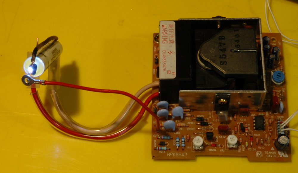
Another MOT supply 13 kV DC 2005, 2008 This charger was to be used in a public display for a can crusher. It uses a microwave oven transformer (MOT) along with the associated diodes and MO capacitors in a voltage doubler arrangement to give 6 kV output. 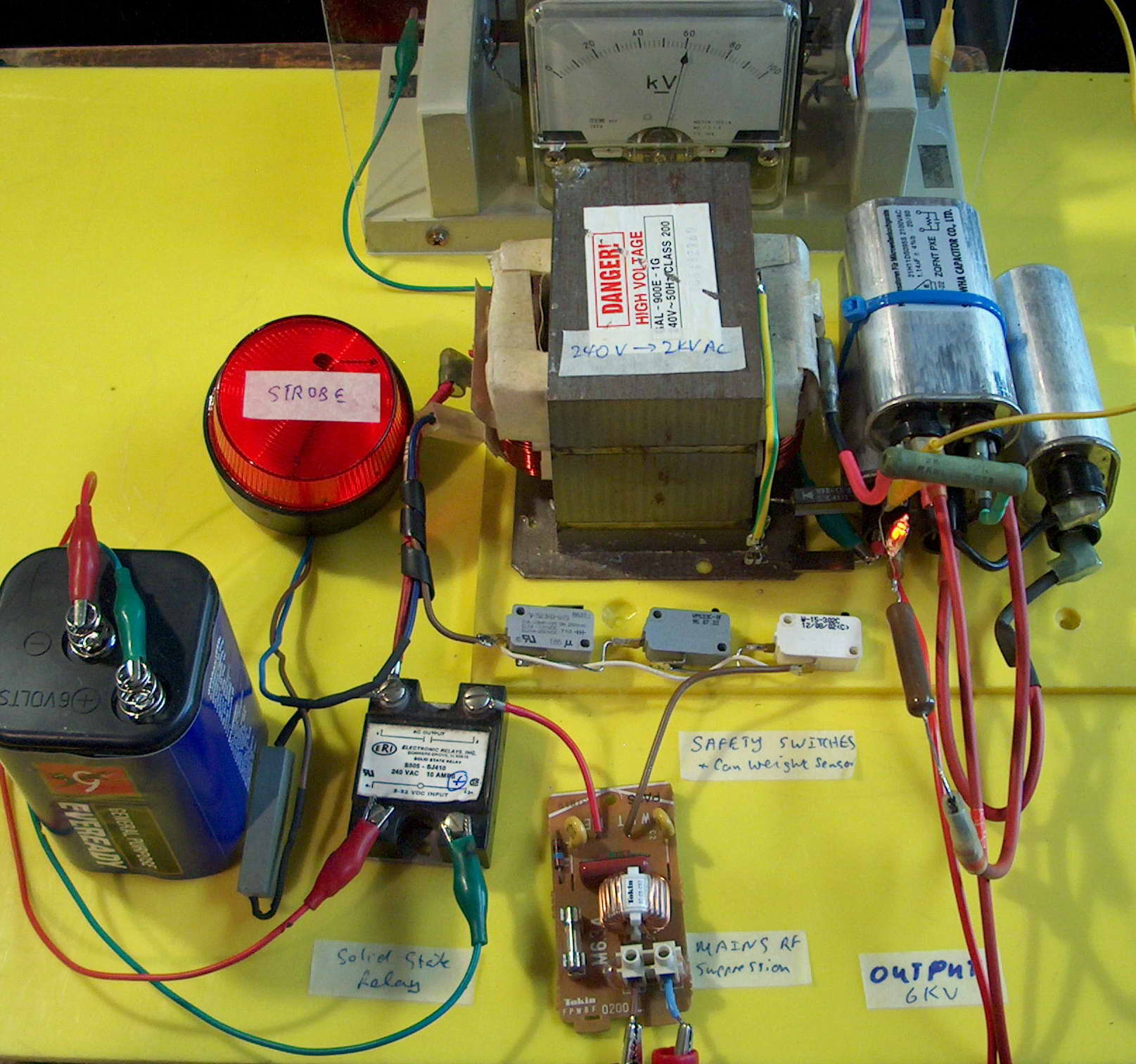
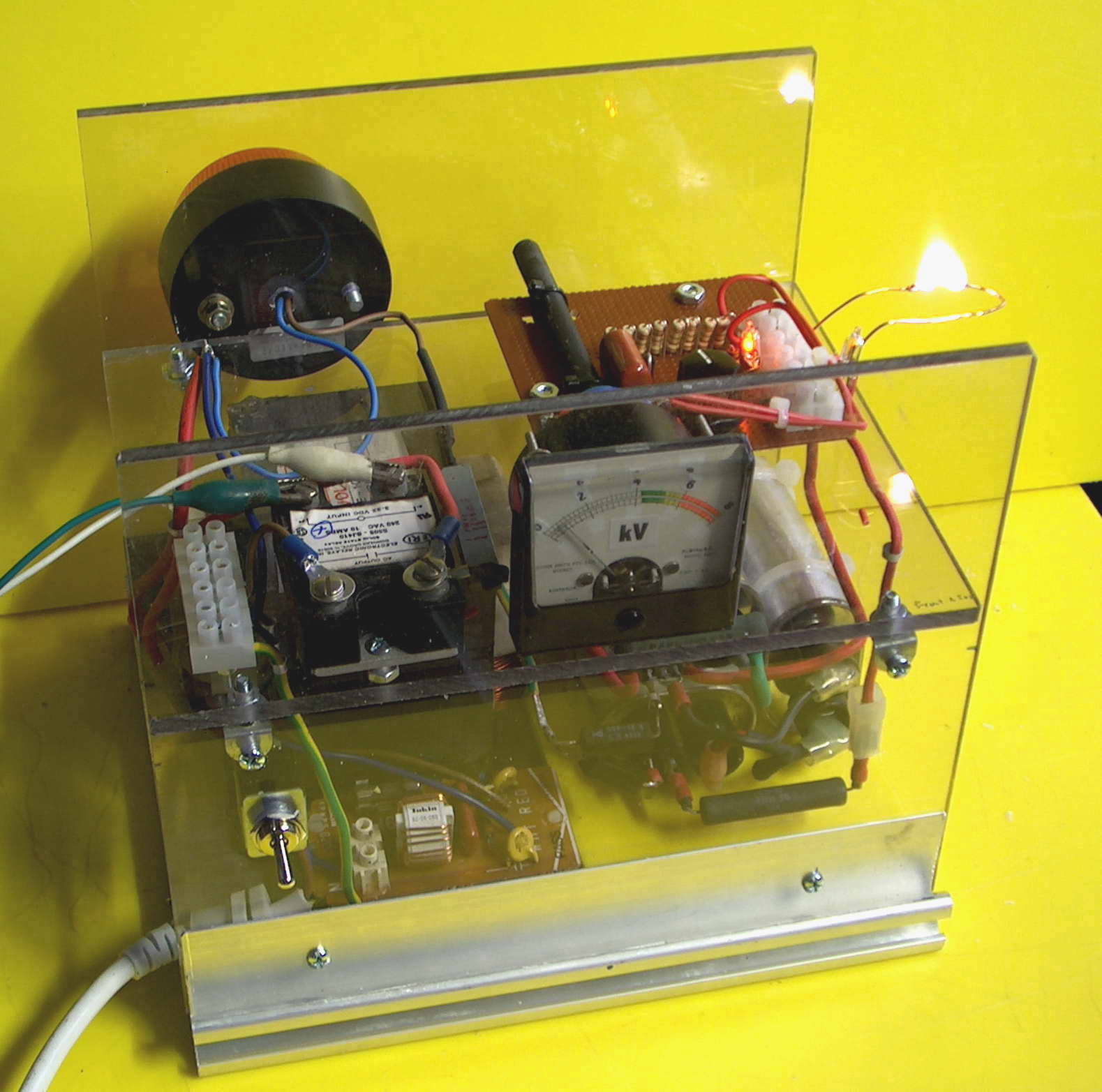 The left photo shows a lash up of the charger, showing the various basic components including a red warning strobe to show it is charged. The right photo shows the partly built charger and 6 kV spark output is shown (drops to less than 1 kV once arc starts). To keep the HV and mains isolated and still feedback the voltage, I send pulses into a ferrite rod which will be picked up and trigger the solid state relay to turn off once the voltage has risen to the desired level. I have rewired this supply with an extra stage for higher voltage and added some big power resistors. This is to be used for charging my big capacitor bank.
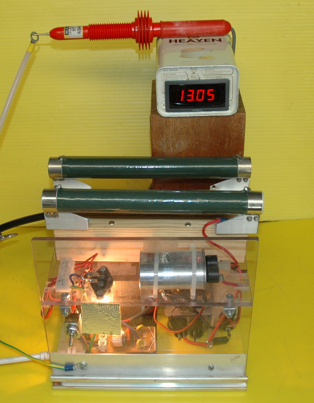
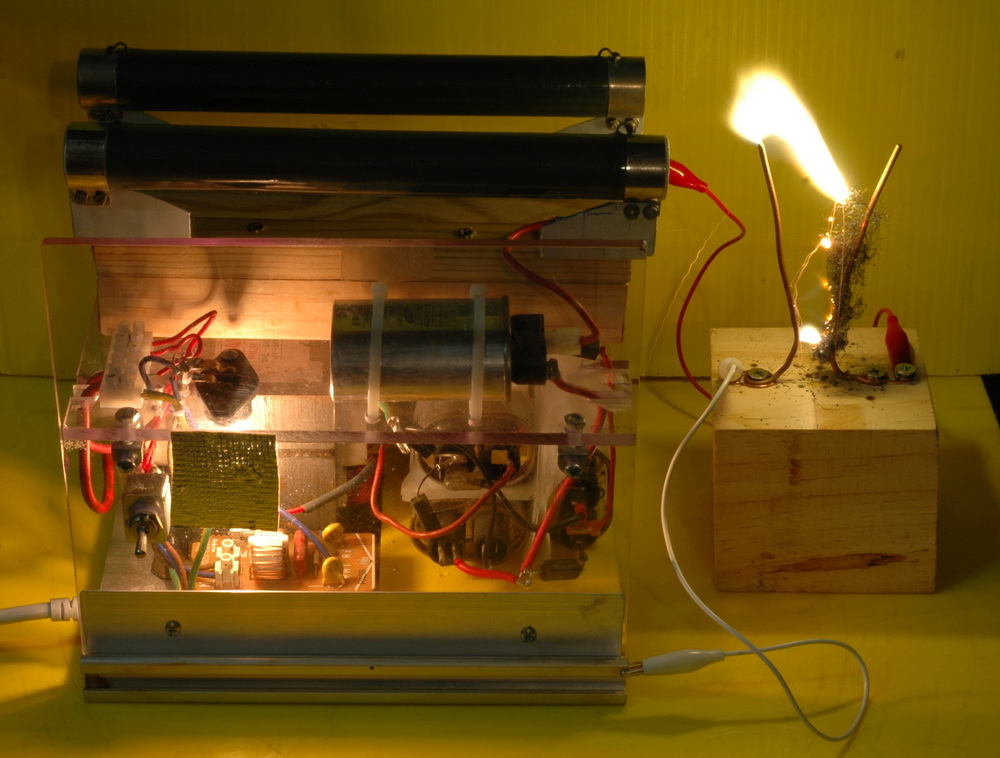 The photo above shows the latest reincarnation of this supply. Now with extra stages to boost to the 13 kV shown here plus the addition of two 50 kOhm 100 W resistors as current limiting. This is to handle the higher voltage of my big cap bank.
HV supplies from a photocopier 5 kV 2006 I gutted a Toshiba photocopier a few days ago. Lots of other stuff including 2 HV supplies. They have 4 input wires so I was a bit stuck to work out how to get them to go. This is how I did it. 1 Work out the supply voltage from the main power board. Most things seemed to be 24 V rated so I went with that. 2 Check the small filter electrolytic cap polarity with the broader PCB tracks that connects near the input wire connector, to determine which is positive and negative. (No, positive is not the red wire – that’s just in movies where they defuse the bomb) 3 Connect the supply – start with 12V to make sure minimal current drain at this stage. 4 By trial and error touch one of the two remaining wires to earth. Bingo its running. Cut off the other wire. Draw is about 130 mA 24 V no load.
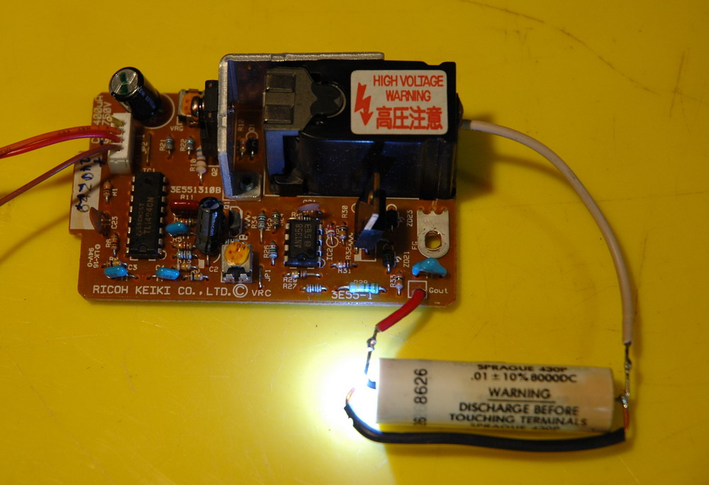
The left photo shows the larger supply outputs 5 kV DC, 3.8 kV AC and a few smaller voltages. I have added a cap to show it is DC and brighten up the sparks. The right photo shows the smaller supply.
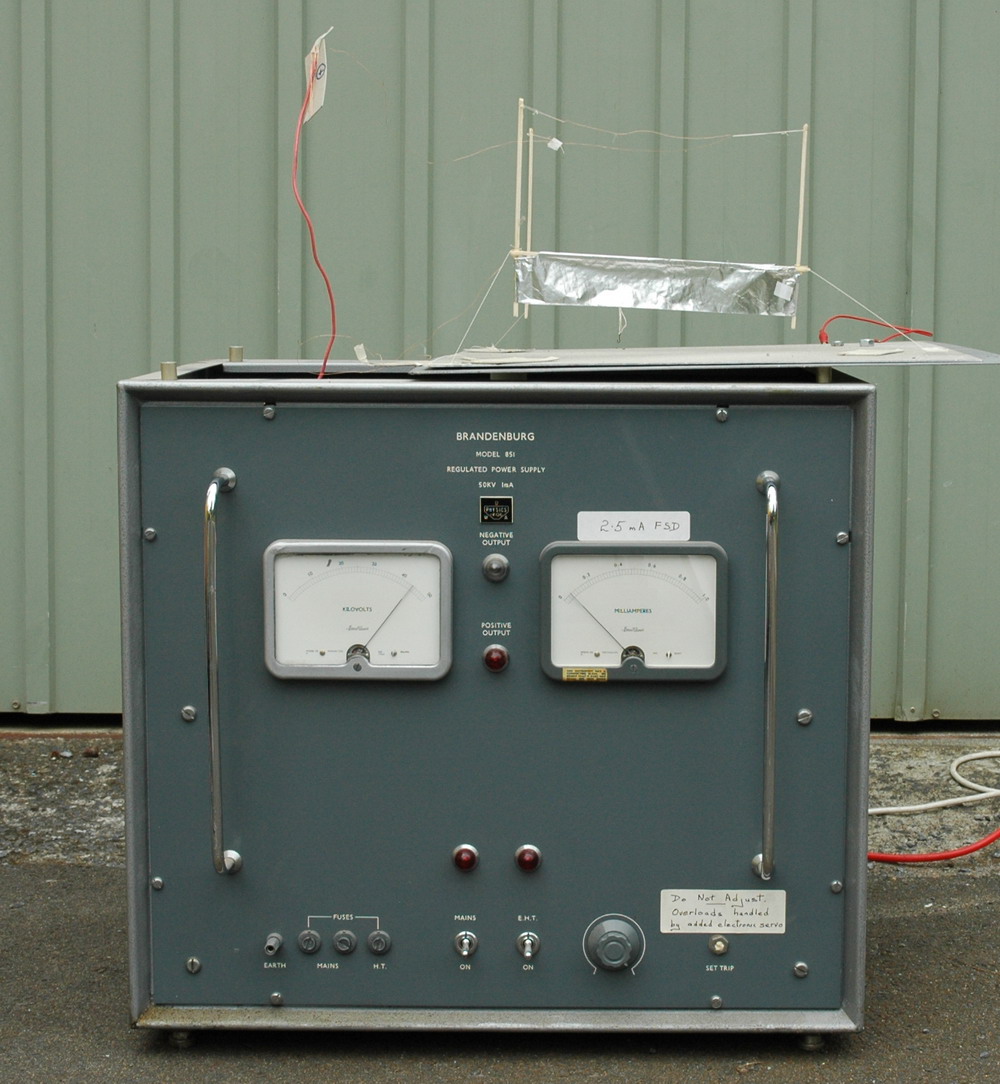
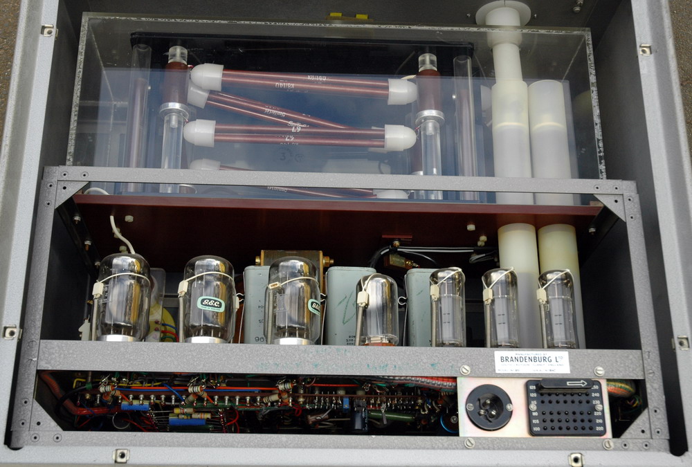
Valve regulated supply 50 kV AC 2006 An old 50 kV 2.5 mA regulated supply was a throw out from the Physics Dept. Worked with minor repairs and a good dusting. It uses 18 valves (remember them – before semiconductors) driving a large flyback transformer and a 6 stage C-W multiplier. Quite nice for a lifter supply if you don’t mind the 40 kg weight for a supply that puts out only 100 W.
Xenon lamp ignition supply 50 kV AC 2008 An old 50 kV supply was an ignitor for an 8 kW short arc xenon lamp used as an ophthalmic coagulator in days before lasers. Examination and a bit of testing showed a circuit not unlike that of a Tesla coil. It has a 220 to 12 kV transformer driving two 1000 pF doorknob caps in a tank circuit with a spark gap. This drives a big epoxy coated coil to give the sparks rated at 50 kV.
The sparks here are about 1 inch and you can see the multiply stacked gap firing as well.
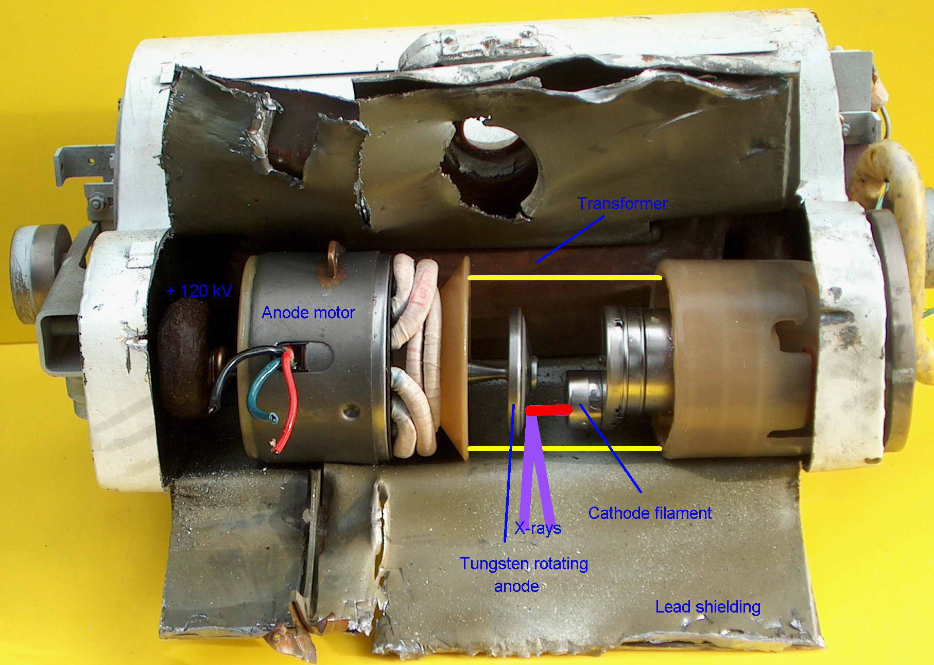
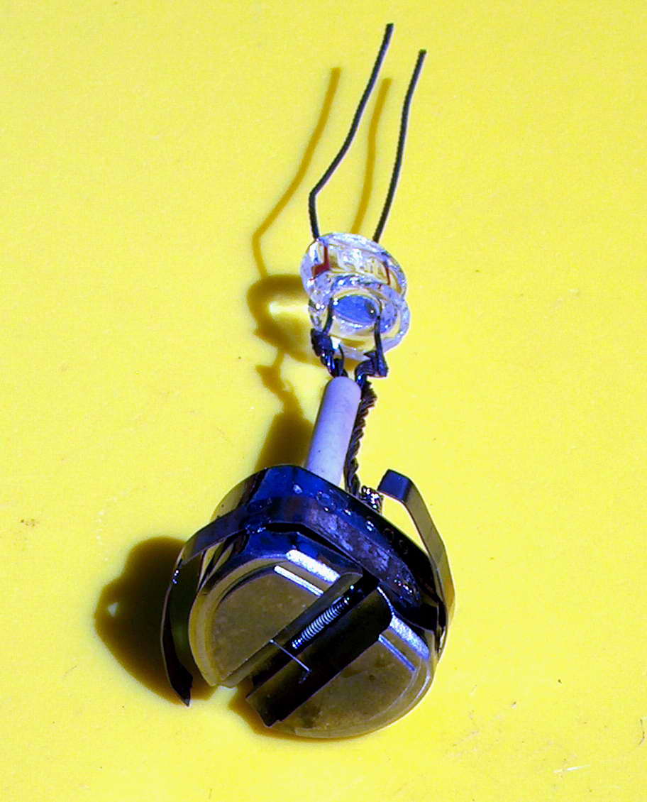
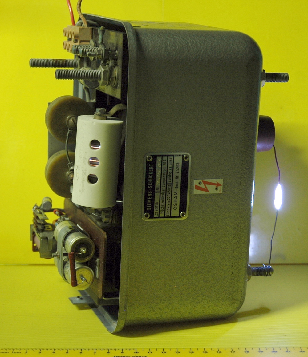
This is the internals of a Siemens 120kV x-ray tube head which includes the transformer (not rectified) and a rotating anode under oil sealed and lead shielded. The glass has been removed with the outline shown in yellow. The electron beam is shown in red and the x-rays in purple. The induction motor is outside the glass and works well on 250V with a phase delay with a 1 uF capacitor on the additional windings. The right picture is the filament on the cathode electron gun which I have joined to some glass feed through wire from a neon tube. This is an x-ray transformer that I have had lying around for years. It comes from an x-ray head with tube enclosed and is rated at 168V in 125kV out. I used an angle grinder to get it out of the lead lined container.
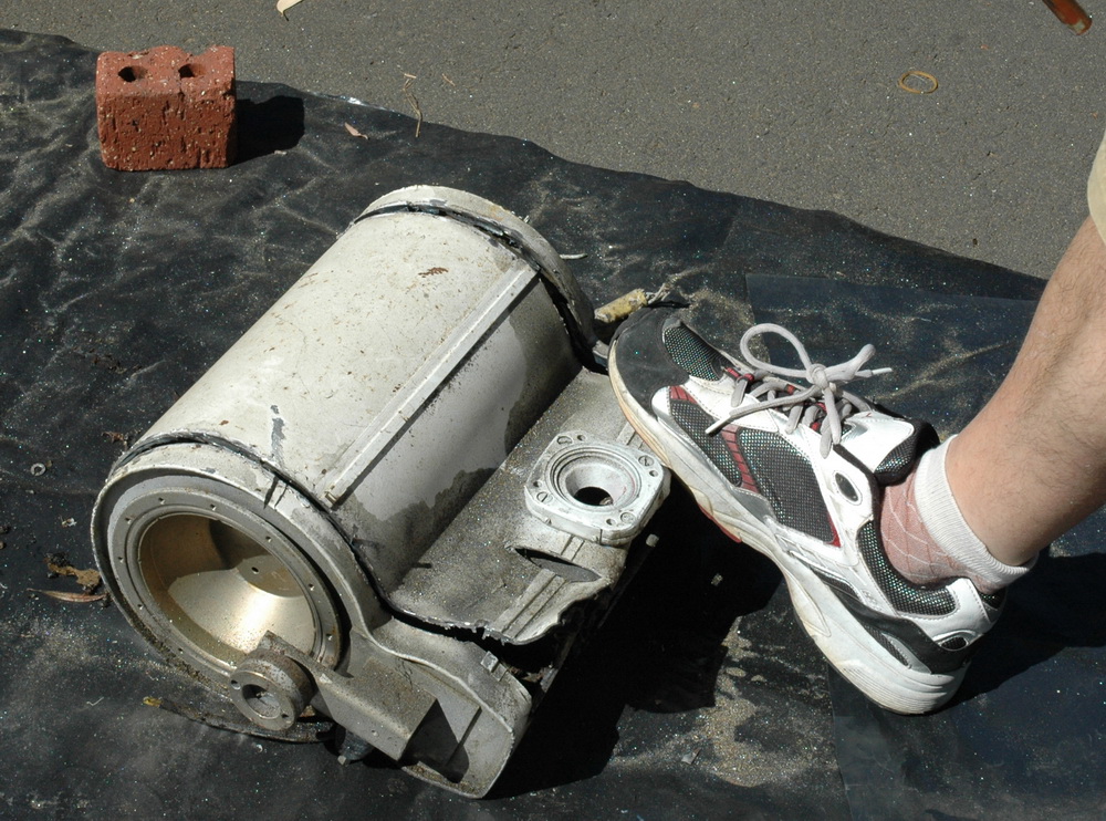
 Unfortunately the HV winding was open circuit but still gave a 1 inch spark at 100V. I sort of hoped it might do better when I got it under oil but of course it didn’t. It was drawing about 5kW to get that 1 inch spark!
 Van de Graaff generator 2003 This is a static electricity generator of the type used in displays which make your hair stand on end. It uses 2 inch rubber belt with fibre reinforcing which was the only non black belt I could find (black rubber is slightly conductive). Powered by a variable speed electric drill. Top load is 12 inch ducting. I have tried a 10 kV DC charging spray but there was no improvement over the standard triboelectric static generation. Maximum sparks on a low humidity day are about 2 inches. More work needs to be done. Winter and the increased humidity will put this on the back burner for a while. PVC is not ideal as it does tend to absorb a little moisture and polypropylene is better.
Water resistor 2008 I needed a resistor to handle a moderate amount of power and be adjustable. To do this requires typically large and expensive ceramic resistors. A simple approach is to use water filled plastic tubing with the resistance controlled by the addition of a salt such as copper sulphate. Copper connectors form the electrodes. 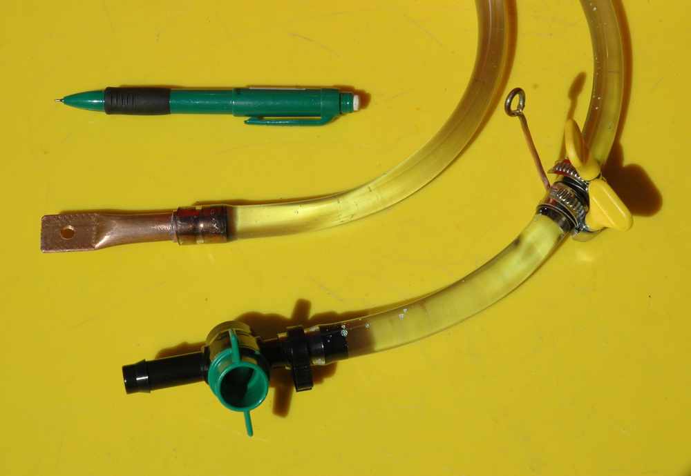
The left photo above shows the ends of the 2 m x 10mm tubing with copper tubing connectors and valve to allow air release or to replace the water if it becomes clouded or for a resistance change. The advantage of this construction is that it is not specifically inductive so sparks, like Tesla sparks will not try to jump across adjacent windings. The right photo shows sparks from a 60 kV supply. The resistor was set at 200 kOhms. The heat was enough to cause cavitation either with boiling or electrolysis but it survived fine without leaks.
Related pages
Try something else
 Ulexite
External links
Photo Date: