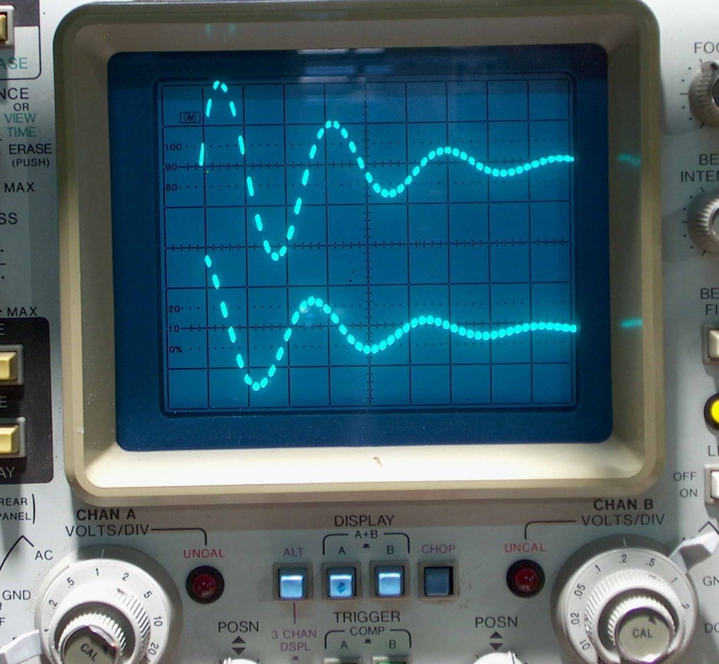
Measurement of High Current Pulses (or my multimeter doesn’t have a 100,000 amp scale). The upper trace shows a peak current of two squares (20,000 A) and lower trace a peak voltage of nearly 2 squares of around 5 kV. Note how the current lags behind the applied voltage.
“Continue reading” for more details and photos.
Measurement of high current pulses involved with can crushing presents a challenge. The initial pulse is short (25 microseconds) and the current oscillates back and forth several times in a resonance that is around 16 kHz. To understand this look at the oscilloscope shot above. The upper trace monitors the current with time. Time is 20 us per division. The initial current rises, then falls, then reverses as the energy stored in the coil’s magnetic field returns to the capacitors and back several times in diminishing amounts. Energy is drained from this process by heating and disrupting the can.
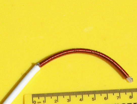
This is the device I made to do this: a Rogowski coil integrator.
To measure these currents without connecting wires to the high voltage, I use a small inefficient current transformer which does not have a magnetic core. This is the Rogowski coil. There is no magnetic core to saturate so the pulse response is good. It is a transformer so cannot measure DC, however. The primary of this transformer is the single big cable that carries the current to be measured.
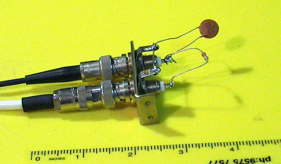
It will respond to the rate of change of magnetic field or current so has to be “integrated” using, in my case, a passive setup with a resistor of 2.2 k ohms in series followed by a parallel capacitor of 0.01 uF. This is to allow for a high frequency, fast pulse being a lot more efficient in transferring power than a low frequency, slow pulse. High frequencies will get “shorted to ground” increasingly.
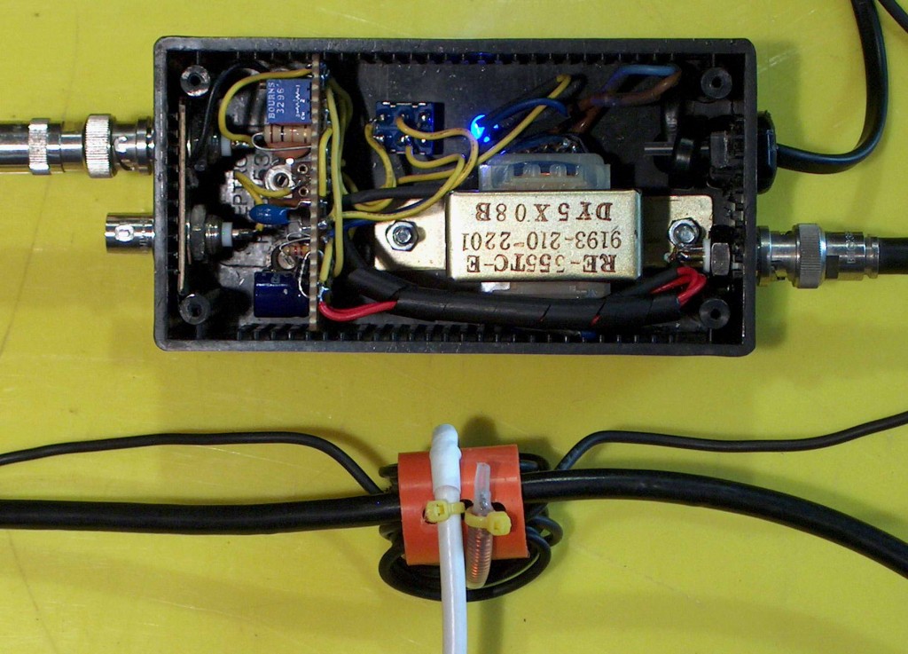
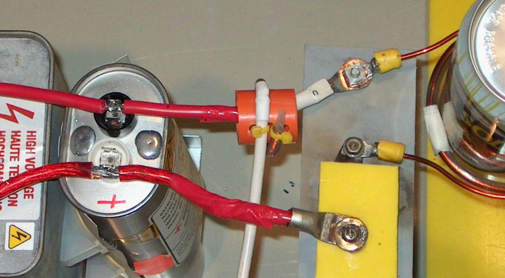
The winding of the Rogowski coil onto flexible coaxial cable. The coax centre is the return wire. The right photo shows the Rogowski coil wrapped around the main cable. The big advantage is that high current cables don’t need to be disconnected and the frequency response is not limited due to the iron core as in a current transformer.
So far so good but it needs to be calibrated to work out what current in the main cable gives what output of the Rogowski coil. This is best done at the frequency concerned ie around 20 kHz.
Testing with two different methods showed an output of around 1 volt for 850 A at 18 kHz.
Now for more flexibility I have made an ‘active’ Rogowski integrator using a fast integrated circuit op amp and a few bells and whistles.
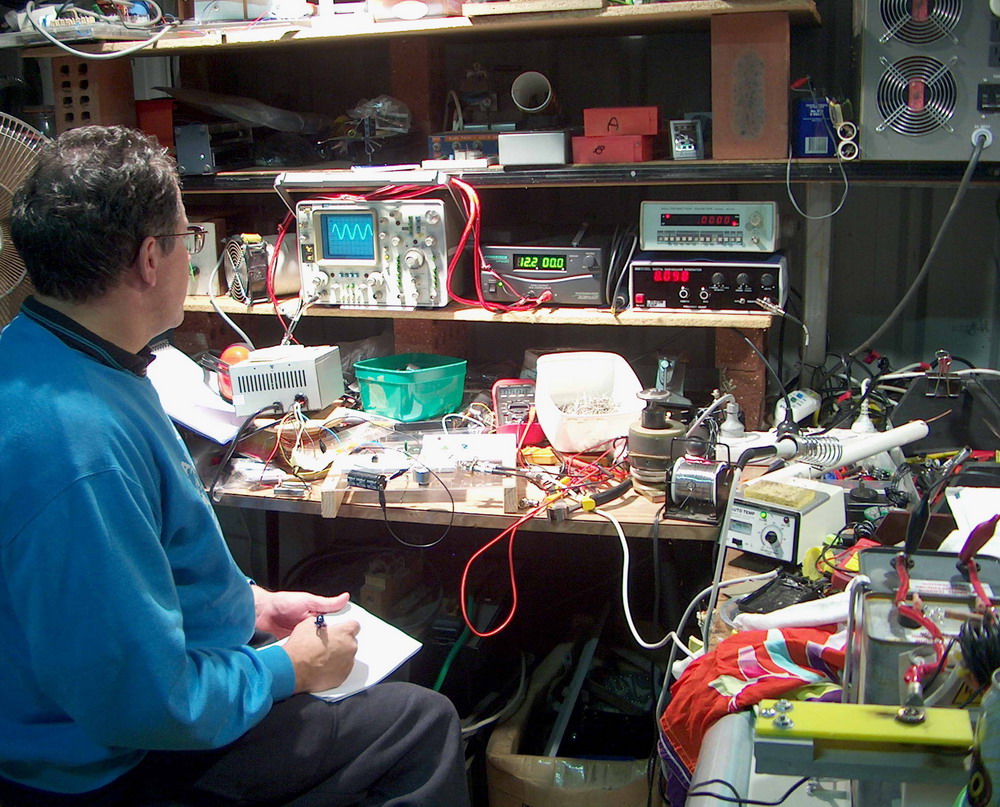
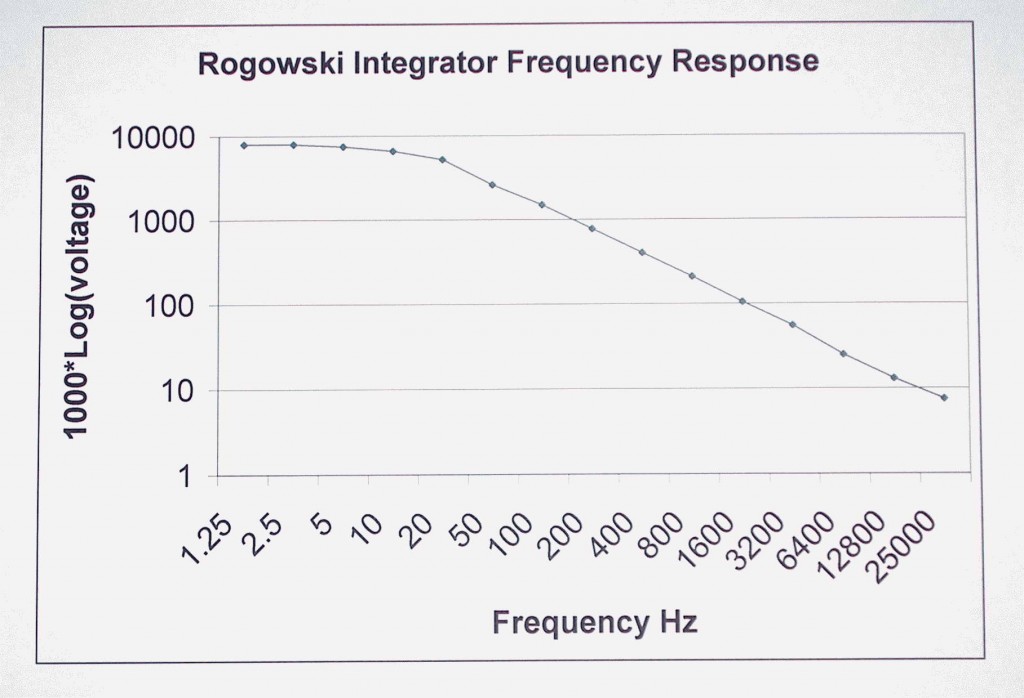
Here is me at the workbench working on calibrating an active integrator for my Rogowski coil using a TL072 op amp to replace the previous passive integrator. The frequency vs output voltage for the active integrator is on the left. Calibration was at 50 Hz but should be OK to 25 kHz from the graph above. It uses about +/- 16 V supply which is poorly regulated but current draw is only 3 mA. Output waveform is read on the CRO. High frequency output at 18 kHz is about 10% below that expected from the 50 Hz calibration.
I have added a peak and hold circuit with the intention that this can be read from a multimeter and hence be useful for the majority of coilgunners and other using pulse power who don’t have a CRO. I have had to go through a bit of a learning curve to deal with some offset problems which are now largely fixed. The peak and hold is not really useful (since I have a CRO) but the time constants for a 60 us pulse to be held for many seconds are beyond a single IC and I need a voltage follower at least and probably a dual peak and hold with two different time constants.
So, where is the circuit diagram?. I don’t know. The original link died, particularly with the dual stage peak and hold. Here is a simple single op amp integrator.
Related pages
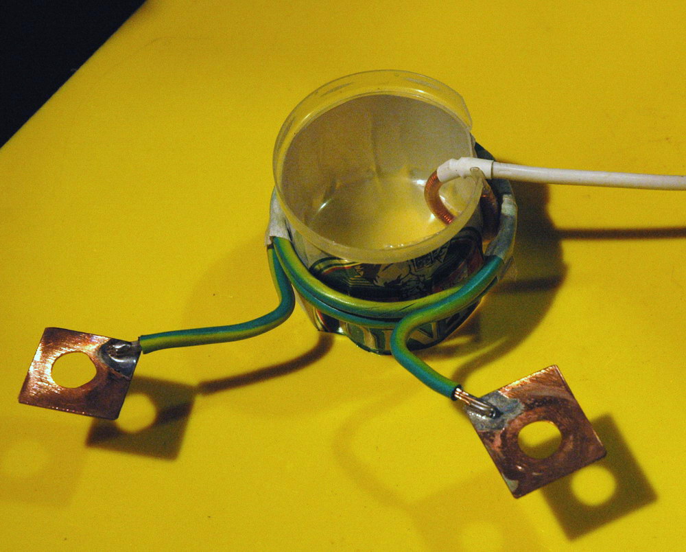 Measurement of current WITHIN the can
Try something else
External links
Photo Date: April 16, 2005
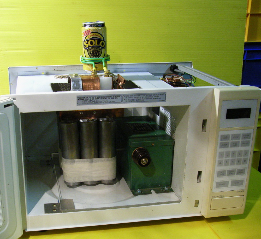 Can crusher 3
 Spinthariscope