Ok, I reckon that there is not enough ingenuity and resourcefulness going on in budget coiling these days.
For more details and photos:
So, on the 4HV forum, I proposed a prize of $US 50 to be paid by me to the person who makes a Tesla coil with the longest sparks from a standard microwave oven.
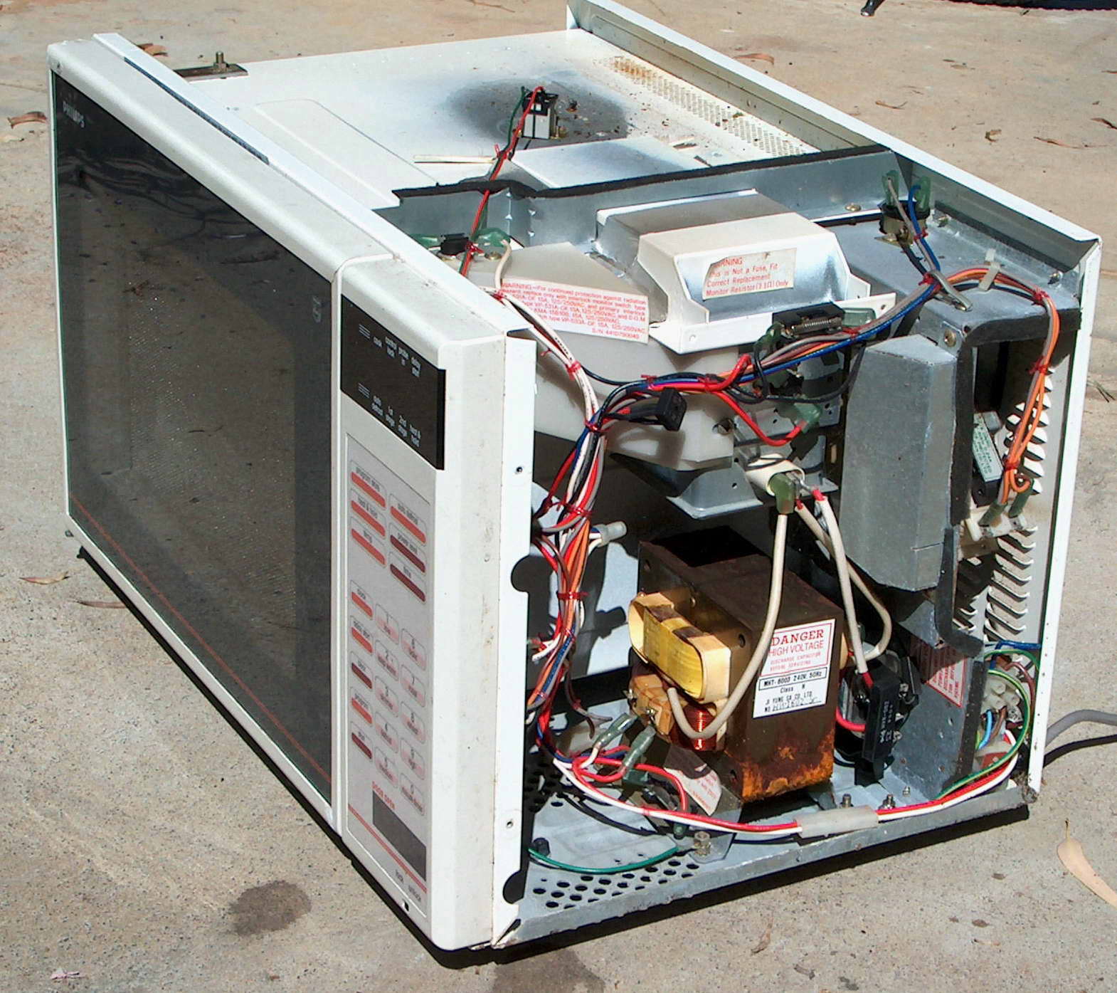 Above: A standard microwave oven with lid off.
The rules were:
One standard domestic MO (microwave oven) less than 1000 W to be obtained free.
MO must be the transformer type not the inverter type.
Only the parts of one oven to be used. No other parts to be used apart from solder, hot glue or epoxy in reasonable amounts (not large amounts to make secondary formers).
This also means no PVC, tape, paper or other extraneous substance.
How you adapt the internal parts is up to you.
Progress, results and sparks must all be photographed to confirm use of only parts of one MO are used. Spark length measured from the photo with a ruler adjacent.
And the result? Well no one won it. I didn’t get the time to complete mine before the deadline. However I have done it – just 9 days late. Shown here with 1/2 inch sparks only but best in development has been 1 inch and plenty of scope for improvement with better design.
Here’s how:
Power supply is the MOT. This needs current limiting and this is achieved with a 150 nF capacitor and the voltage is boosted by a one stage multiplier using the MOT diode to give 4 kV peak. Note that power is taken off across the diode not across the cap to get the voltage multiplier effect. Hey what’s this about a 150 nF cap? Where is that in a microwave oven? Well that is the key to this project. The 1 uF 10 kV DC mylar and oil cap (that is in all non-inverter MO’s) needs to be taken apart and unwound. Lengths of the multilayered dielectric and foil are taken out and cut to length. It took about 10 feet of the windings to make 150 nF. This is perhaps only 30 % of the total. New electrodes were added.
 Above: The mylar cap drained of oil and unwound, then rewound with 4 redundant layers for the tank cap.
Tank cap. This is a 1 nF cap. The technique is similar but I retained the original electrodes from the cap to use in this section as they were better suited to a high current. Construction of this cap was different in view of the much higher voltage/current and frequency stresses. It used about 30 % of the length of the cap windings. The plates were only about 1 foot long by 2 inches, however I used two sections of foil/dielectric between them. The foil was not connected and was kept to equalise voltage stresses. All in all something like 12 layers of mylar and 2 foil layers separate the main electrodes.
Being mylar they do warm up a bit.
Spark gap This is two aluminium electrodes (from the frame of the MO fan) bolted to part of the MO timer circuit board with all the components and printed circuit ground off. It really needs another section to give better quenching.
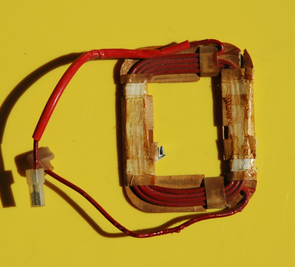
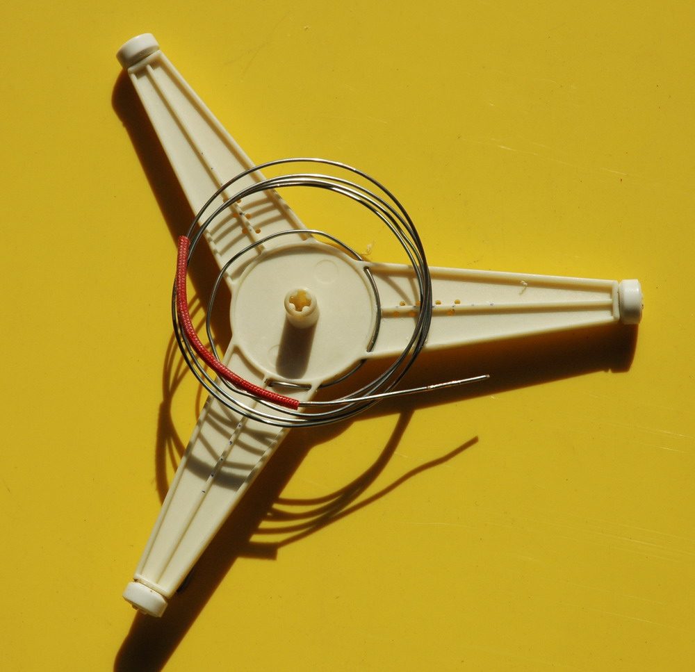
Primary is the MO transformer 6 V winding which is heavy copper. This is stuck on to the 3 legged wheeled frame that the glass food tray sits on and rotates.
Secondary former is the cardboard internal cardboard insulation from the HV cap. It was washed but became a bit soft but still usable.
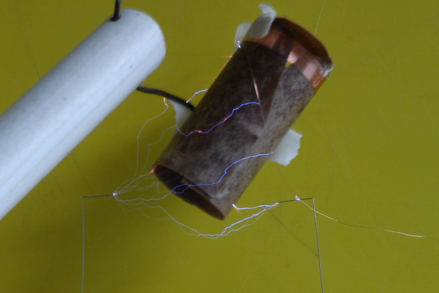 Above: The primary former being HV tested for conductivity.
Secondary windings use wire from the fan motor and less than half was used. The hot glue didn’t stick the cardboard former together properly and the windings slipped and overlapped. I have had some interturn shorting (and may still have) so I can’t really push the power much without a rewind. No idea how many turns.
Toroid I did try winding lots of turns of wire on the fan blades but it didn’t improve the performance. so I just left the metal mesh spacer that sits on the output of the magnetron for a nice colour.
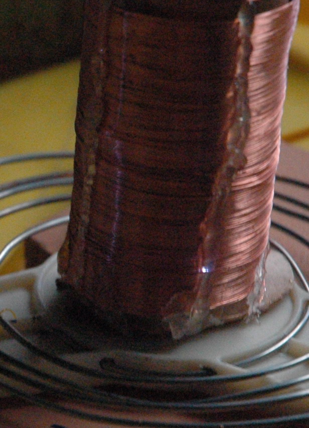 Photo above shows a spark with inter-turn shorting and also a long racing spark suggesting over-coupling.
Left photo above shows the full setup with the MO transformer feeding into a voltage doubler formed by the 150 nF cap and diode. The output is taken across the diode to get the voltage doubler effect. This means the diode is across the spark gap which does look unusual but it should give 4 kV peak to fire the spark gap. The tank cap is 1 nF.
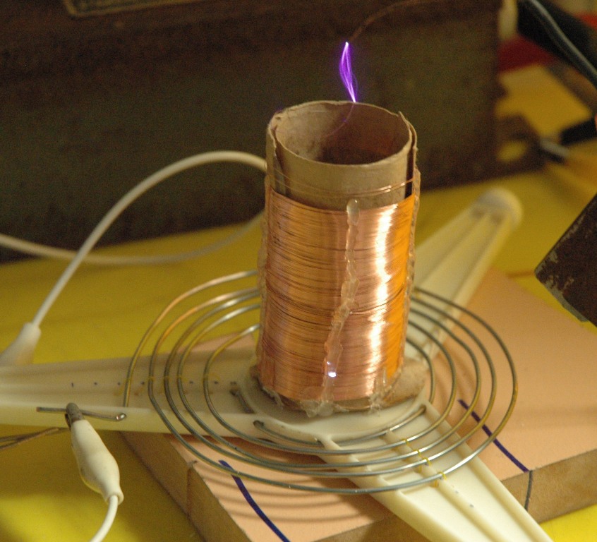
Above: This coil is run from 4 kV from an NST with 2 spark gaps for testing (rather than the MO supply). Not fabulous performance but the proof of principle is there are plenty of opportunities to do better. I was reluctant to retune and push harder as the 150 nF cap kept blowing and having to be rewound with a section cut out. The secondary is overlapping and may not tolerate a higher voltage although I suspect it may have a shorted turn already which is why performance has dropped despite the power increase.
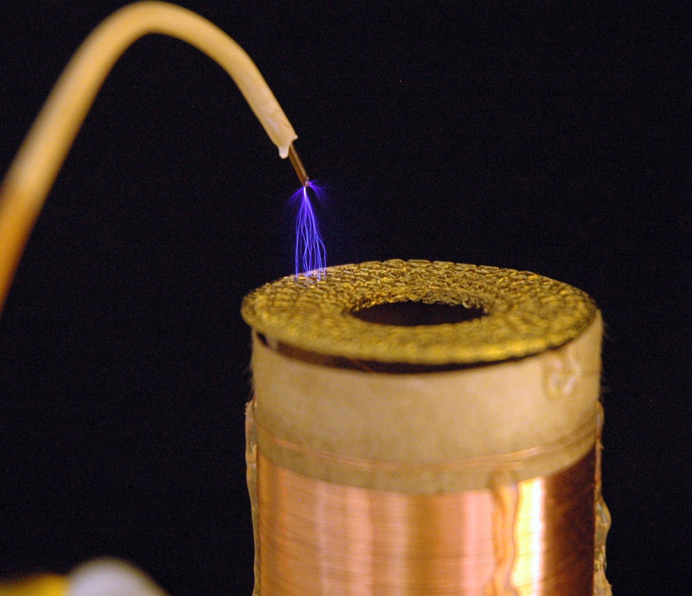
Above: The completed Tesla Coil made from a single microwave oven parts has smaller sparks
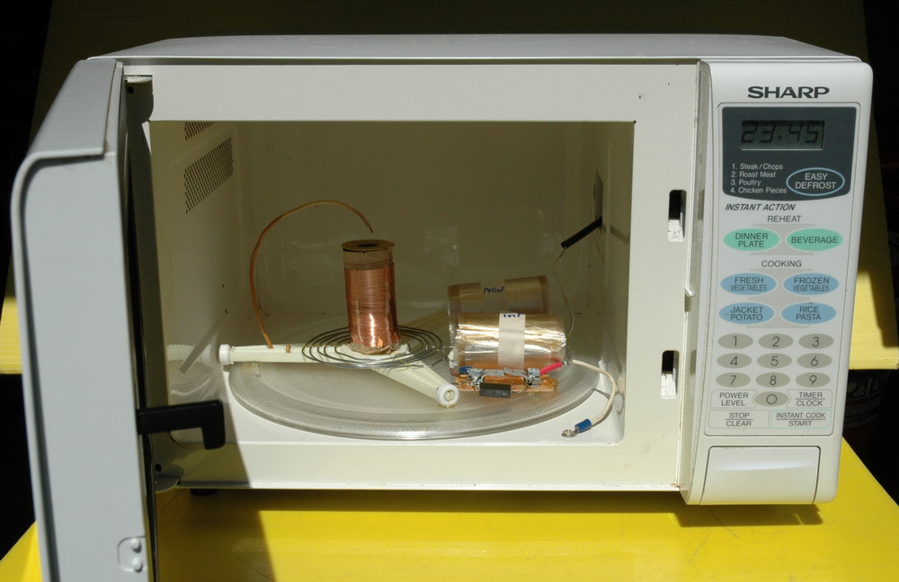
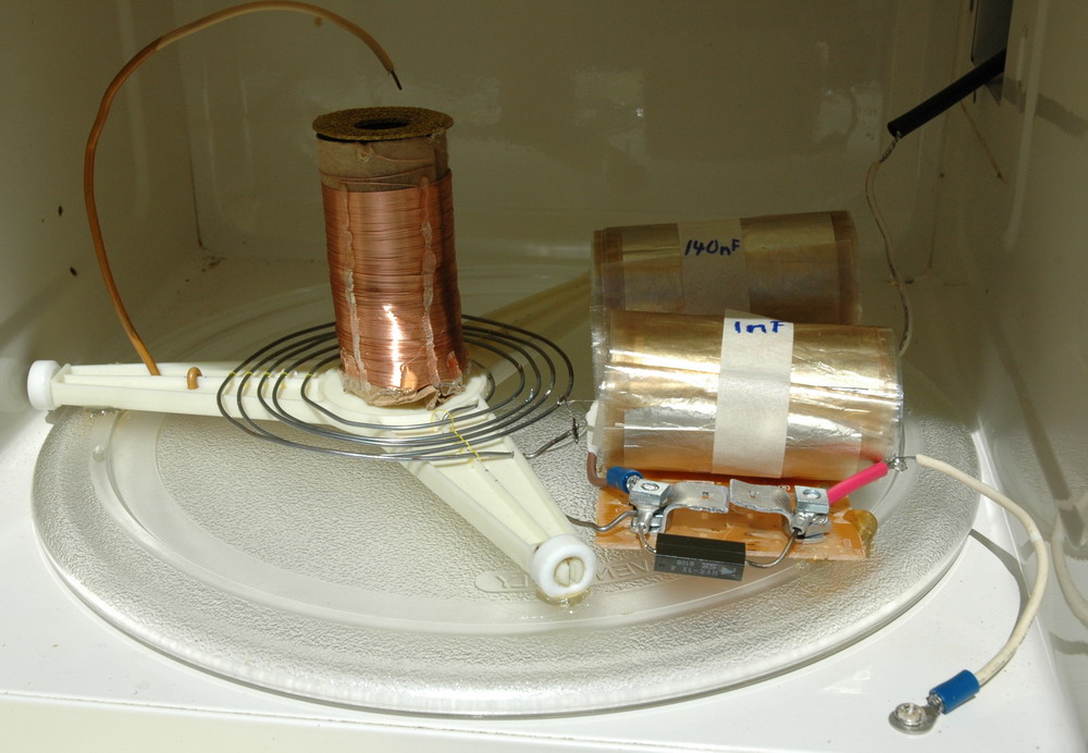 And finally put back in a MO with the electronics still functional so you push START and STOP to run it!
Related pages
Try something else
External links
On the 4HV forum, I proposed a prize of $US 50
Photo date 2006

 LED rope tricks