 My first magnetic levitation project setup lifting a NIB magnet working after a week of adjusting and testing. A NIB magnet with some metal pipe is supported motionless, 1 inch below the coil. “..look Ma, no hands..”
“Continue reading” for development of a display, circuits and components. 6 photos and links.
This was for an exhibit for the Gravity Discovery Centre in Gingin, Western Australia, as part of an ‘antigravity’ display. The GDC is the public interface for the Australian International Gravitational Observatory which is part of a worldwide effort to detect elusive gravity waves.
The circuit uses two linear Hall effect devices at either end of an electromagnet. The circuit senses a difference in the two outputs which should cancel regardless if the coil is switched on or off. An approaching magnet disturbs this balance and this this output is fed to a PWM (pulse width modulated) supply for the MOSFET output to the coil. Conditions are set so that there is an equilibrium is setup with the weight of the magnet and the electromagnet at a certain point where it will hover. Hmmm.. magnetism opposing gravity – sounds like ‘antigravity’ to me…


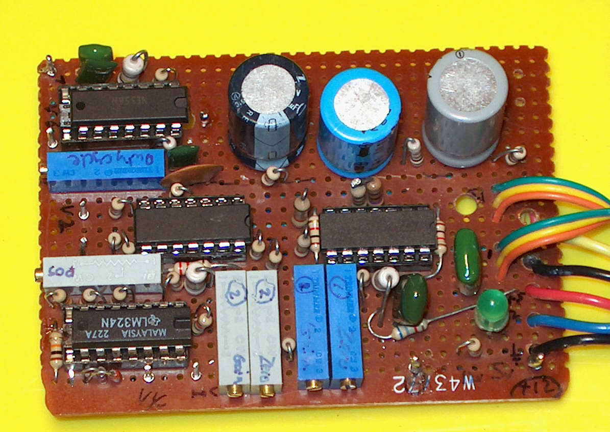
The left photo shows the coil and earlier circuit board. The other two are of the neat side and the not-so-neat side. Alright, so I don’t know how to do PCB’s but, hey this is still running 10 years later.
The coil will draw 10 A at 13 V and is wound on an old solder bobbin. In operation, however, the draw is less than 2 A at 12 V. The drive circuit uses three LM324 quad op amps (of which 9 of the 12 are used) and a dual 555 timer (NE556). This drives a IRFP450 MOSFET rated at 500 V 14 A under the CPU cooler fan. There are two BYV29 500 V, 9 A, 60 nS diodes to absorb the back EMF when the coil switches off. The circuit comes from Rick Hoadley’s excellent magnet site. I have made only minor modifications to his magnetic levitation project setup including reducing minimum pulse width from 4 to 1 uS and using the MOSFET instead of an IGBT.
 This is a standard 200 W ATX computer power supply which is 7 years old. It supplies +12 V 8 A (yellow wire), -12 V (blue) and +5 V (red). It has been modified to include a power switch on the back panel and a divider across the 5 V line with a 24 ohm and a 10 ohm resistor in series. This allows some load for the 5 V line (? need 0.1 A) plus a 3.3 V reference for the orange lead which normally senses the computer board voltage of 3.3 V. I did blow out the first supply I used but no problems since this modification which also powers the LED through a 100 ohm resistor from the 3.3V line. I have tidied up the leads into one multicore cable terminating in a 25 pin plug.


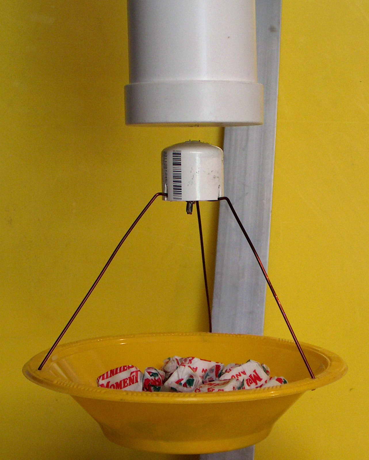
In action with a fancy mount and fitted into a suspended PVC pipe with all the wires tidied up, it can support a dish with 110 g of sweets. (This was for a lunchtime demo). It worked OK but unfortunately I left it running inadvertently for some time and the electromagnet melted through the end cap. Ooops. Remarkably the Hall device and the electronics were unharmed.
I later went on to make a larger more permanent display for the Gravity Discovery Center.
Related pages

Try something else

External links
Hall effect sensors – Wikipedia
Photo Date: Feb 2, 2004