Tag Archives: left photo

Levitation of a coil

A coil being levitated above a copper plate by eddy current repulsion

Eddy current repulsion can provide enough force to give levitation of a coil. The coil was out of a defibrillator output circuit. Don’t know number of turns but the inductance is 10 mH (I think). It is drawing 6.5 A at 100 V AC to get the lift of about 1/2 inch off a 1/4 inch copper plate. It is tethered like a conventional lifter. The power is over 600 W so gets hot quickly.
“Continue reading” for further examples and calculations. 5 photos and links….
Continue reading

Magnetic Levitation Project

Magnetic levitation project success with a magnet and metal tubeMy first magnetic levitation project setup lifting a NIB magnet working after a week of adjusting and testing. A NIB magnet with some metal pipe is supported motionless, 1 inch below the coil. “..look Ma, no hands..”
“Continue reading” for development of a display, circuits and components. 6 photos and links.

Continue reading

Diamagnetism with Bismuth

Diamagnetism with bismuthDiamagnetism with Bismuth stabilises levitation

Diamagnetic levitation using bismuth plates to stabilise the magnetic lift of one permanent magnet by another. This is the classical setup with a small cube magnet between two bismuth plates. “Continue Reading” to see the video, a cool Bismuth crystal, 6 photos and links…
Continue reading

Aus Got Talent – Setup

The Tesla coil sparks are stopped by the earthed protective screen.

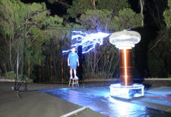
This is how my 2011 performance for AGT was developed from a backyard Tesla coil demo.
The various TV and other videos are on the Australia’s Got Talent – Videos page.
But here is a 7 second animation of the 2 minute act which I will refer to.

Australia's Got Talent

The main stunts I did are these:

Burning CD's for Australia's Got Talent Channel 7 Promotional Photo

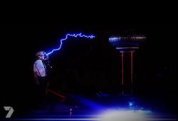
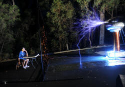
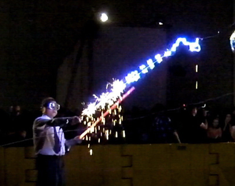
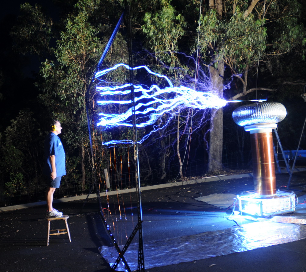
Left photo shows me holding a wooden rod with burning CD’s.  The wooden rod that I am holding goes up in flames. Extra sparkles came from burning steel wool. The right photo shows one of the promotional photos with sparks onto a metal cage that surrounds me .

So how did this all happen?

I was invited to perform in the auditions of Australia’s Got Talent in Perth, Western Australia which screened on May 10th Channel 7.
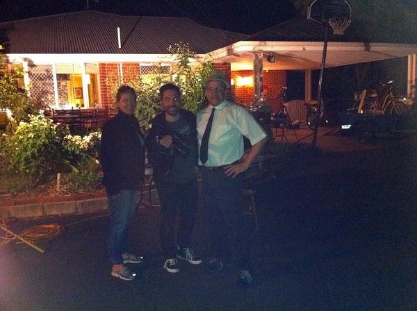
Suzanne (exec. producer) and Paul came to do some preliminary video at my place on November 24, 2010. Auditions were performed in Bunbury Western Australia of 200 people in the local Entertainment Centre and they came to my place afterwards. I was looked up specifically due to the top 5 success of “Arc Attack” in theAmerican equivalent show. This was the first level audition to see if it gets to the full auditions held in Perth in 2011. See the official AGT site.
The result was that I made it to the televised heats in March 20th in the Perth Entertainment and Convention Center. There were major issues with the venue, power, earthing, interference prevention and public liability.

AGT Paul and Suzanne
Firstly the music. An original soundtrack was done by my son, Michael Terren who is an 18yo pianist and composer studying at the West Australian Academy of Performing Arts. The music has a pounding industrial theme and runs for 2:17 mins.

Resonant Air-Core Transformer (Australia’s Got Talent) by Michael Terren Some of his other work is here.
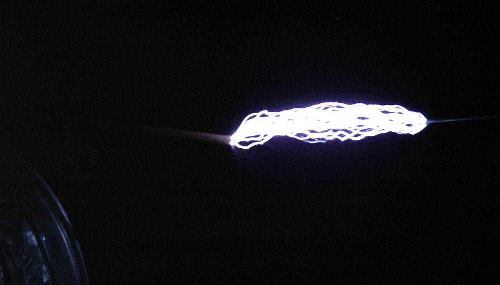
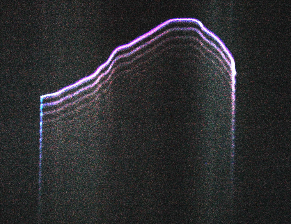
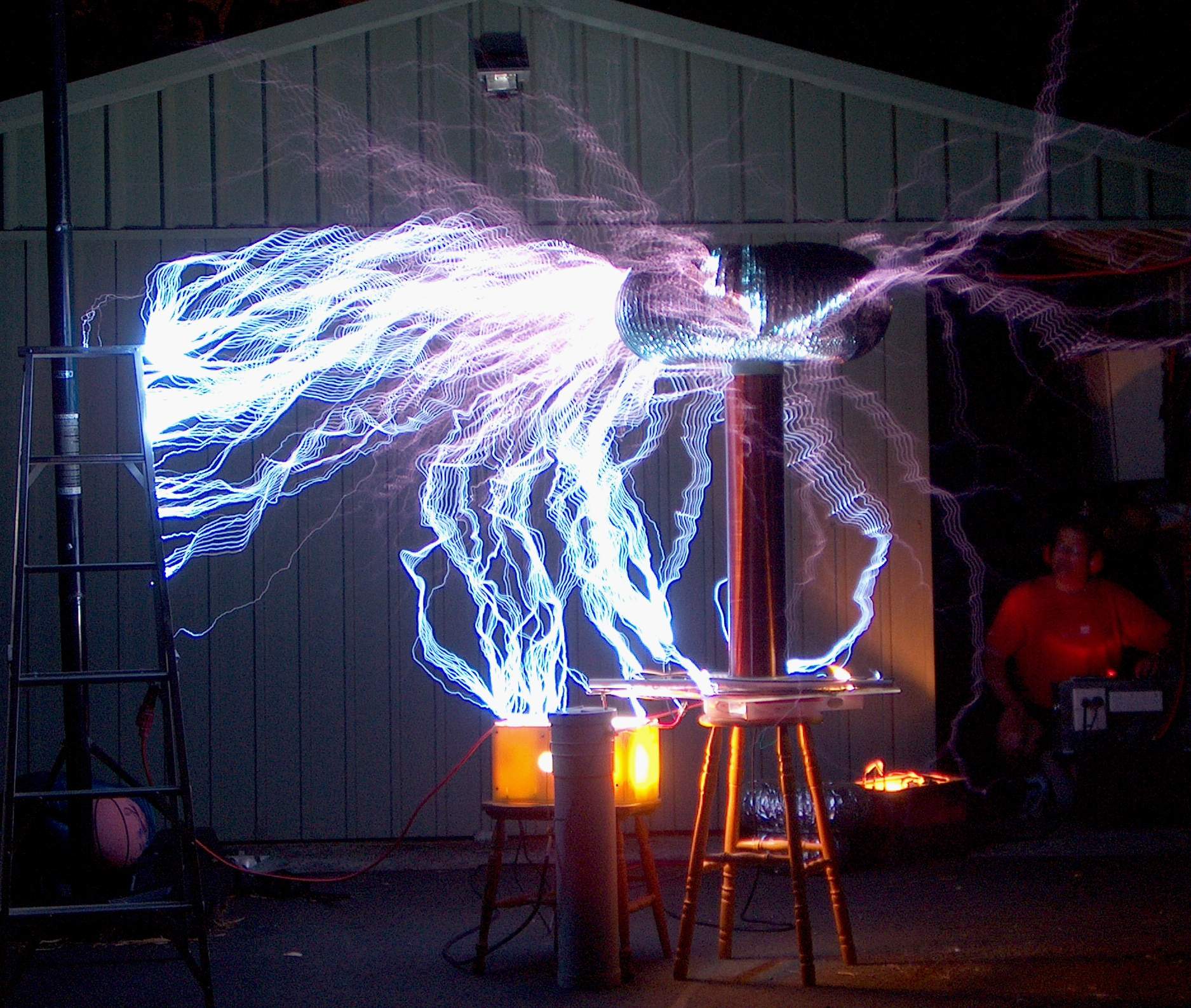
Secondly, crowd protection and iterference reduction in close proximity to judges, microphones and video cameras was achieved by the use of fine wire screens.


AGT Judge Screen 3.5m

AGT Judge screen 3.5m front
AGT Judge screen as planned

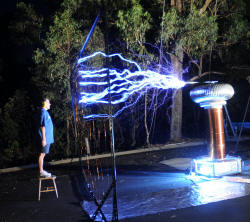
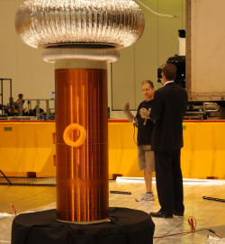
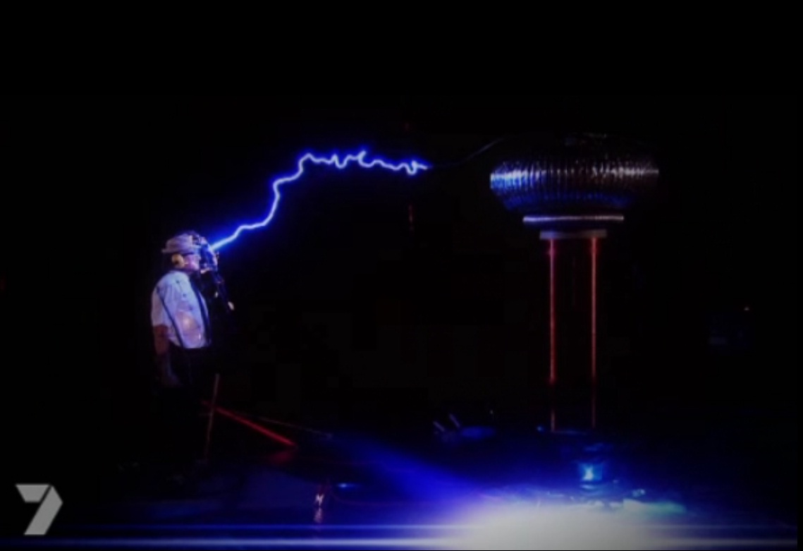
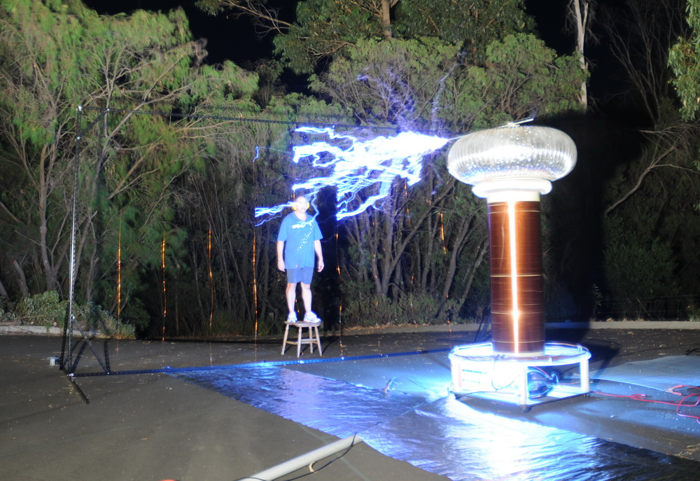
The judge screen is shown above. At 3.5m from TC center, there are strong sparks to the screen but I am quite safe behind them. For the judges (Kyle Sandilands, Dannii Minogue and Brian McFadden) I have chosen a more conservative distance of the screen being 5m away as shown on the right.
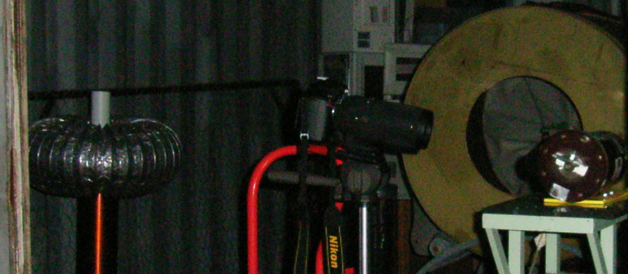
Much other equipment was constructed for this show including a bank of 6 arc welders to be used as needed for voltage isolation or ballast, and two 3 phase distribution boxes. Also extended black backdrops and a vast foil earthing system / partial Faraday cage not to mention a new capacitor bank and power factor correction.

Trailer Bunbury
AGT in a very big room
AGT team
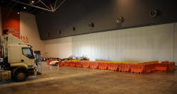
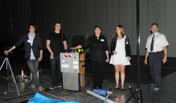
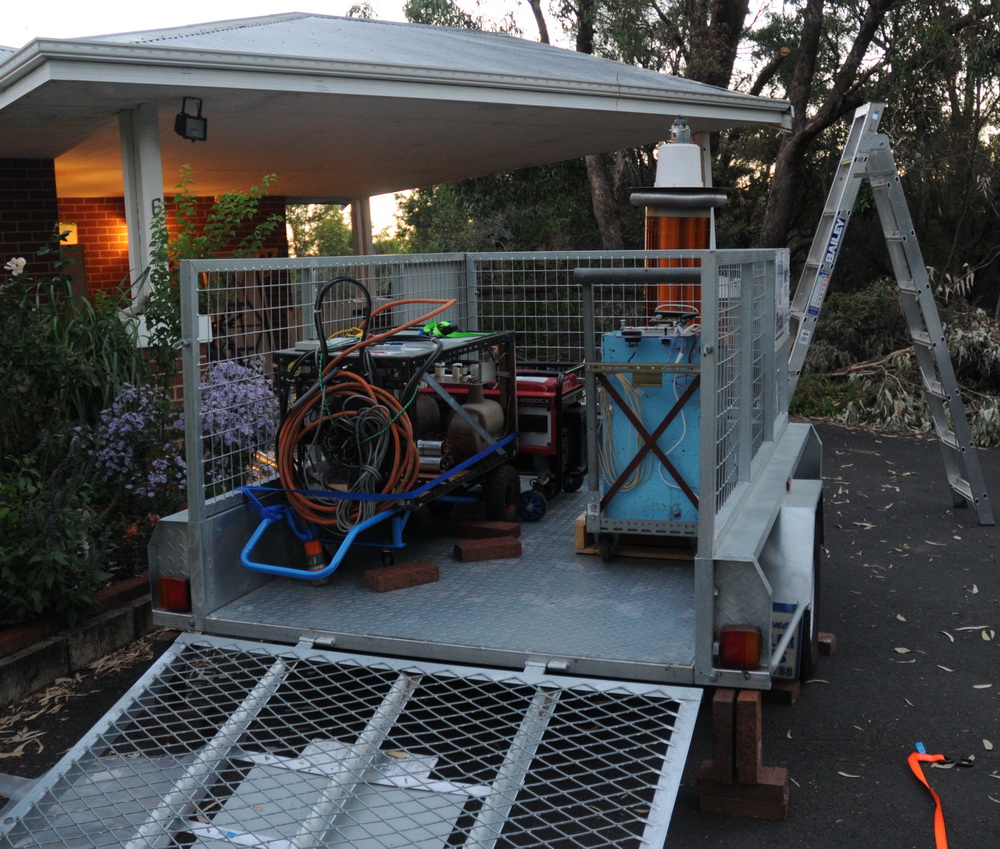
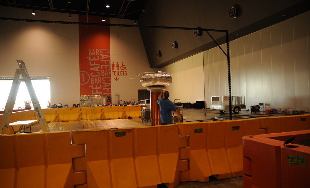
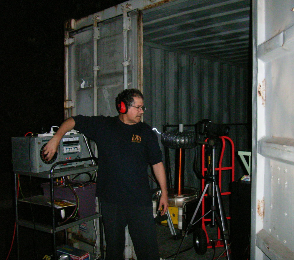
 Above left shows the generator, capacitor bank and TC controller getting packed. Center shows the enormous pavilion and my fenced off area. They removed the carpet so they could drive trucks in. Right shows my team of (L to R) Michael, my son who did the music, Chris (son), Jane (wife), Jaime (Chris’s g/f) and me.

Early setup
AGT Safety Oficer
AGT final setup
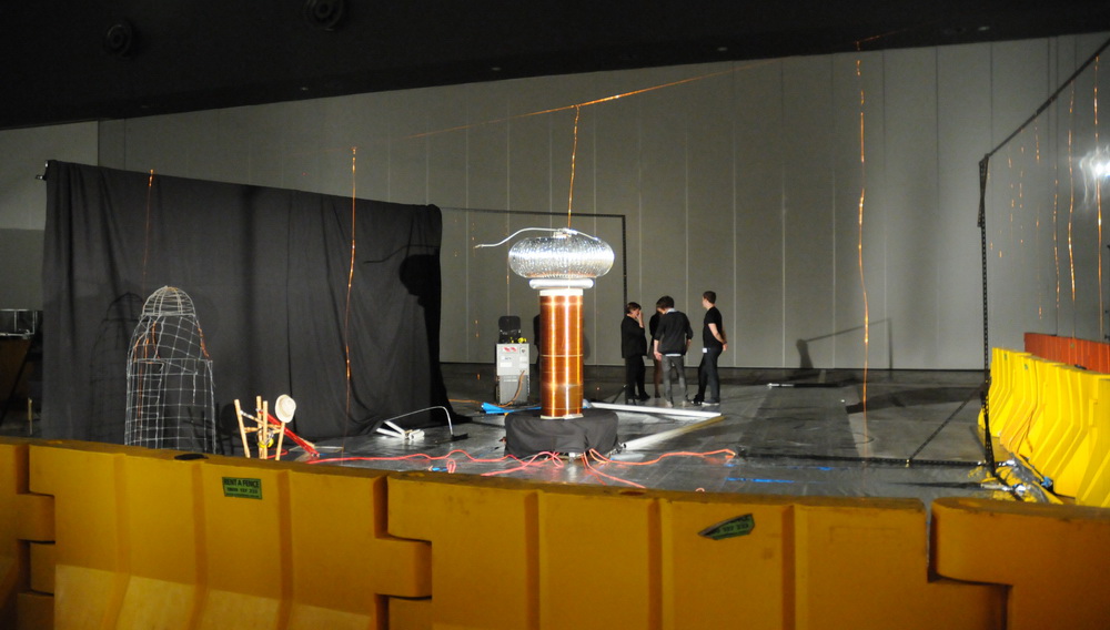
Above left is the repositioned enclosure and center shows one of many discussions with the safety officer, Joshua. The right photo is the final setup ready to go. Note there is a network of suspended wires completely circling the TC for protection and reduced fields for camera safety. On the day I decided not to go with the rigging of an elevated shield in view of the height of the roof. Note the large foil covered area of about 50 feet which is the RF earth which connects to all the elevated wires and frames. There was no direct link to the pavilion building earth but there may have been through some expansion joint covers. The mains earth was kept separate. I ran the ARSG gap and blower gap motors through back to back arc welders as isolation transformers. There was no clear return path for capacitative currents induced into the 50 foot ceiling. There was no ground available for over 100 m that was not a mains ground. Using this method of a “Faraday cage” open at the top, there was no evidence for interference with sound or cabled video cameras. It was close enough to have sparks within perhaps 10 feet of the judges (it could have safely been a lot closer with my design – tested to within 2 feet). The grounding with downwires from the frame allowed confidence in preventing capacitative voltages appearing on equipment and operators. It is my belief that this is more important than RF interference. Certainly this was as close as my operators have been and no tickle from holding the variac!

Modern Thinker

Sparks and sparkles. What's there not to like?

The “Modern Thinker” above is my Tesla coil sparks interpretation of Rodin’s classic statue the “Thinker”. It conveys the concept of the modern electrical age with the barrage of electrical interference in our lives. So much is happening and demanding our attention that it is difficult to “think”.

Continue reading

High Speed Spark Photography 3

HV Rotating Mirror Streamer Hit1

This technique looks at microsecond events in the Tesla coil sparks. Here are some Tesla shots with the rotating mirror setup described here. The TC is my 4 inch one. It was set up for 4 then 6 inch sparks between pointed electrodes to a grounded object. Power was 4 MOT’s and current draw about 10A 250 V so enough to have a reasonable power arc rise in the centre if it got going. The distance from camera lens to mirror was 30 cm and from mirror to TC 140 cm.
 

The left photo shows the the setup (taken with my older camera) and shows the TC at left. The camera (center) picks up the image from the rotating mirror on the right. The right photo shows the TC running with spark just behind my shoulder.


The left photo shows the reversed image through the rotating mirror (stationary for this photo) showing the toroid on the left. The right photo shows the single spark with a series of up to 5 parallel sparks. Each space between sparks is 50 pixels which is 5 us period or 200 kHz. This implies a 100kHz waveform if there are two sparks per sine wave. Seems in the ballpark for the running frequency of this coil.
Note that this is not the banjo effect seen on a windy day which is just the spark gap firing rate of 100/120Hz for a synch gap (or 1100Hz with my fast asynchronous gap which was running flat out as I didn’t have a third variac setup). This is 100 – 1000 times faster.
Very high speed observations of spark growth can be made with streak cameras which use a photomultiplier tube to displace and magnify the image. It is about 3 orders of magnitude faster than what I am doing. It gives propagation rates of spark leaders of 10^9 cm/sec (approx 1/30 of speed of light) whereas I can only achieve 10^4 cm/sec.
Still, I was never expecting to be able to see things like that with equipment found around the home.
On the other hand, streamer growth has structure on very slow timescales which is why they are interesting to look at. In short, you can see them move so there are things happening at all sorts of timeframes from nanoseconds to seconds. Streamer brightness is much lower however but should register some interesting images.
Interpretation of streak camera stuff is easy if sparks are a straight line but become difficult if angled or branched so a blurred mess is a possible outcome when I try this with streamers.
I’m not sure how “useful” this will be but I hope to get some streamer data sometime.


The left photo shows an arc with no following 100 kHz ring down like in the last photo. The right photo shows a bright arc with faint ring down.


The left photo shows gaps in the bright white arc channel filled with faint purple arcs. The right photo shows detail of the initial spark which has a clear central channel on the enlarged view.


The left photo shows the ionization around the stainless steel electrode which does glow red hot at the end of a run although that is too faint to see. Thecenter photo shows that the ionization is sometimes delayed by 5 us after the initial spark strikes. The right photo shows an unusual streak that I suspect is the spark channel hitting a dust mote and burning it up.


The left photo shows a streamer which is about 12 inches of an 18 inch spark from the toroid side on the left. I was throttling the variac back to try to just get streamers and few hits. It is quite different. Time axis is downward. The initial streamer sparks (the top one) can be broken into perhaps 6 consecutive channels (5us apart = 2 pulses per 100kHz). Although it is difficult to be sure, only the last one makes it across the screen then a 10us gap then the main arc hits. Interestingly there is no ring down on the main arc, however the distances are greater and intensity is down. The center photo shows two different streamers which are unrelated but overlapping. It shows the variability in intensity of subsequent spark channels and the gap before the main arc forms. Perhaps this is a harmonic effect and the spark channel is actually of greater energy than the channel before The right photo shows the streamer ring up sparks of as many as 8 sparks in a row.
I guess the new information from the rotating mirror stuff is that streamers enlarge with successive cycles and ring up leading to a spark that connects. Sparks that connect (often) have a ring down. Not really unexpected from the CRO pics but nice to see it directly. So streamers ring up and sparks ring down – easy to remember.

Photo Date: 2009

Liquid Oxygen

Liquid Oxygen adhering to the top of a magnet due to paramagnetism

I made about 50 ml of liquid oxygen by passing medical grade oxygen through a condenser in a dewar of LN2. The photo shows it adhering to a magnet, due to it’s paramagnetism.
“Continue reading” for more interesting liquid oxygen stuff including paramagnetism.
Continue reading

Magnetic Levitation 2

Display at Gravity Discovery CenterMy magnetic levitation display keeping a magnet spinning in mid-air.

After my earlier proof of concept Magnetic Levitation 1 it was time for a serious setup.
“Continue reading” for full display set-up in a science museum. 8 photos, video and links…
Continue reading