Category Archives: High speed spark photography

High Speed Spark Photography 3

HV Rotating Mirror Streamer Hit1

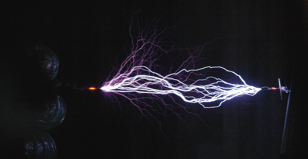
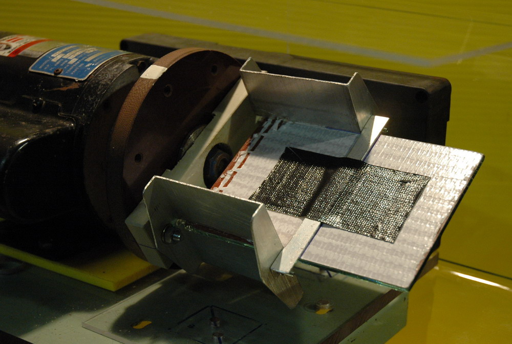
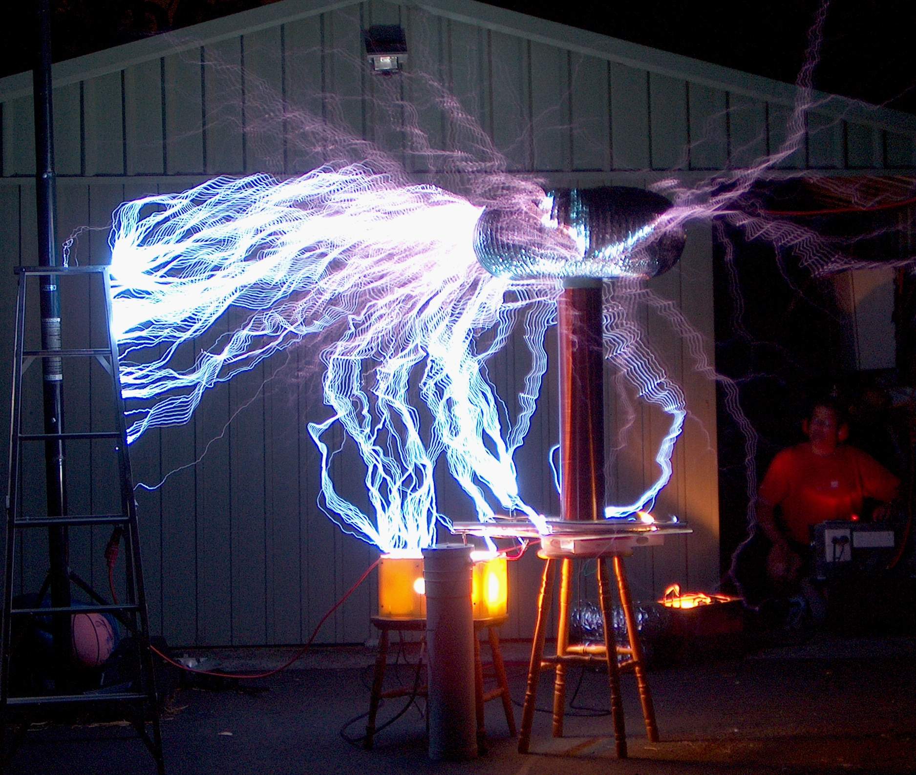
This technique looks at microsecond events in the Tesla coil sparks. Here are some Tesla shots with the rotating mirror setup described here. The TC is my 4 inch one. It was set up for 4 then 6 inch sparks between pointed electrodes to a grounded object. Power was 4 MOT’s and current draw about 10A 250 V so enough to have a reasonable power arc rise in the centre if it got going. The distance from camera lens to mirror was 30 cm and from mirror to TC 140 cm.
 

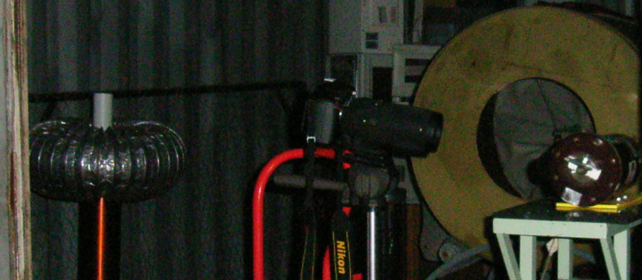
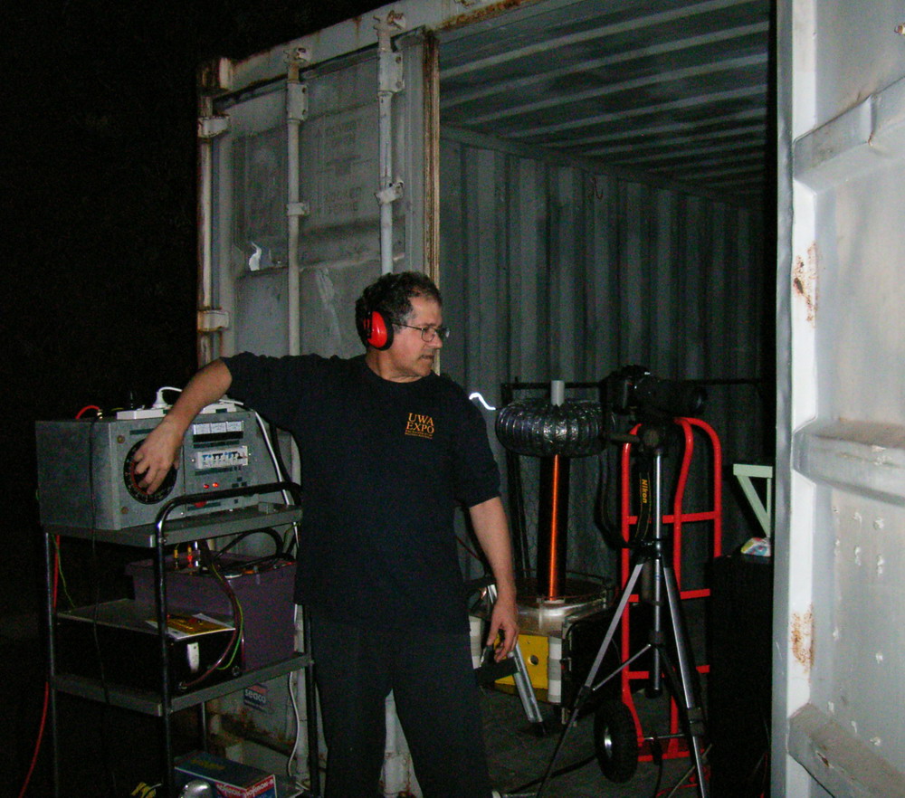
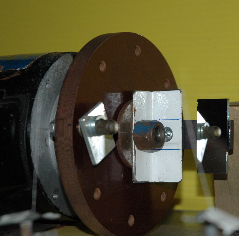
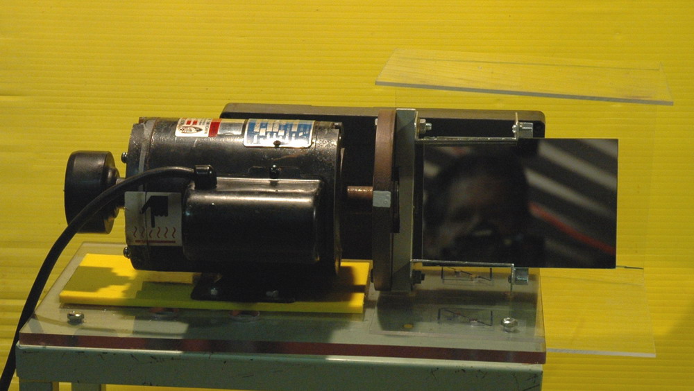
The left photo shows the the setup (taken with my older camera) and shows the TC at left. The camera (center) picks up the image from the rotating mirror on the right. The right photo shows the TC running with spark just behind my shoulder.


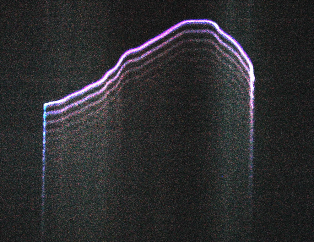
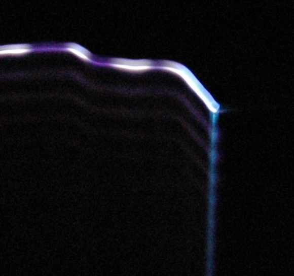
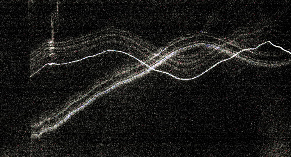
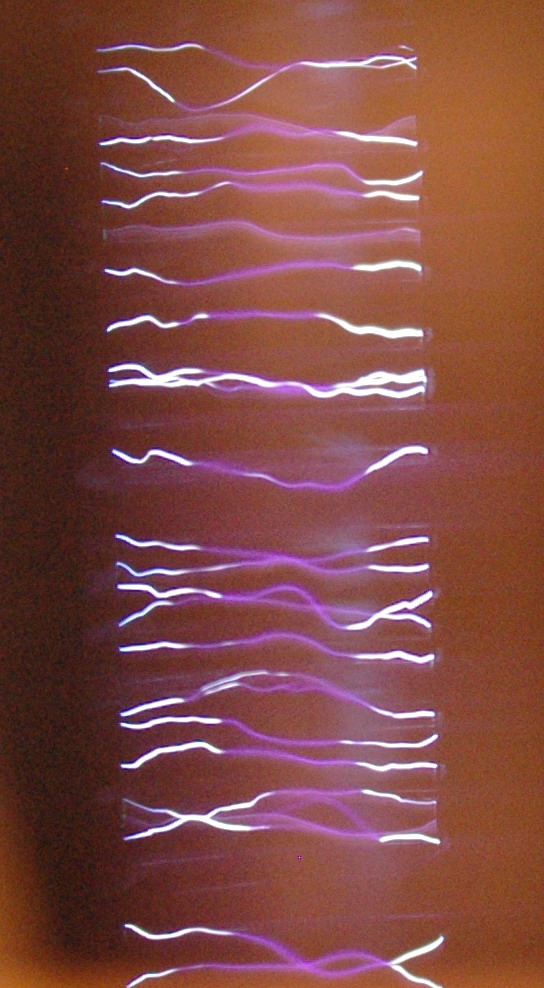
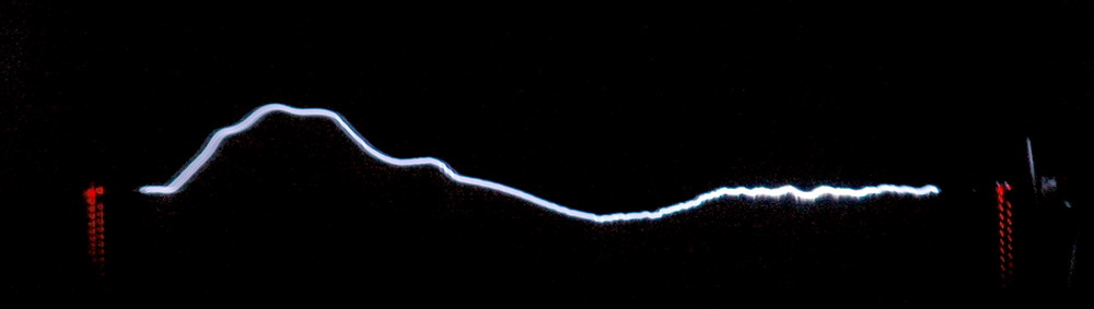
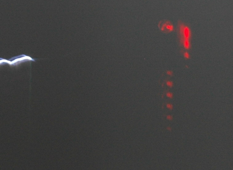
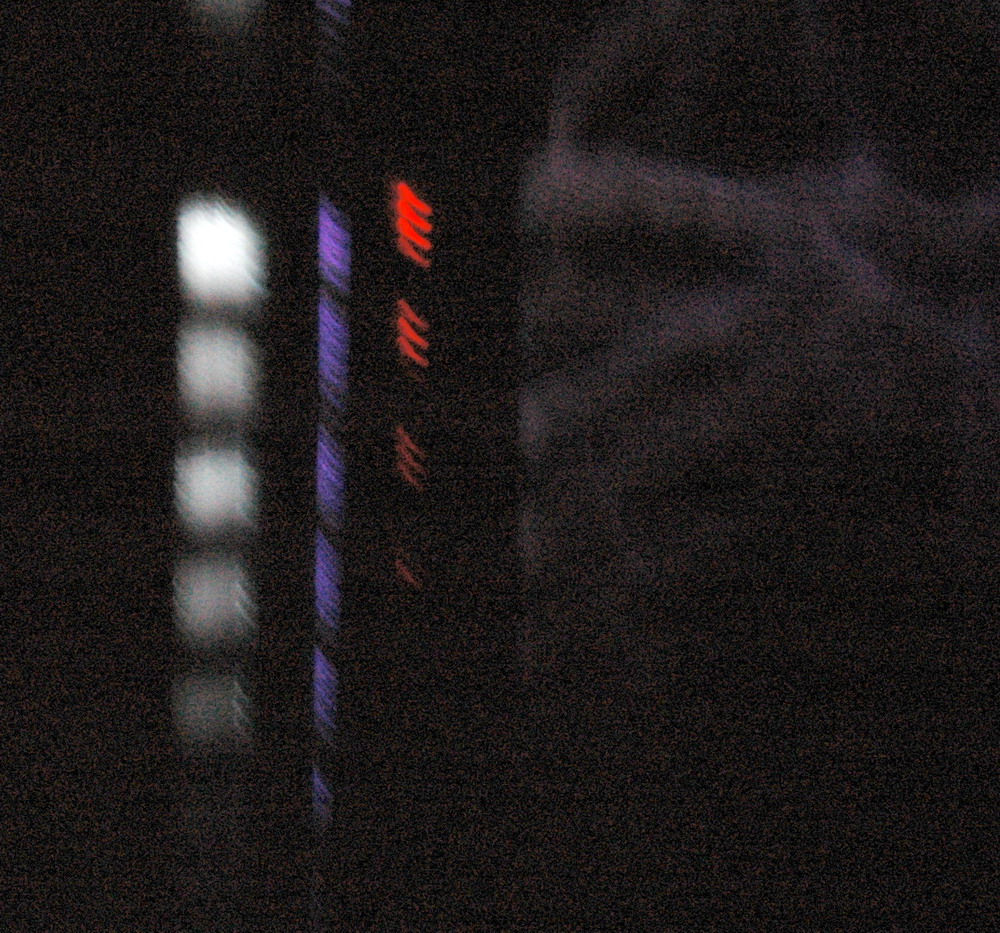
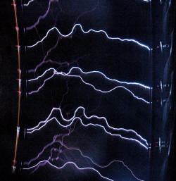
The left photo shows the reversed image through the rotating mirror (stationary for this photo) showing the toroid on the left. The right photo shows the single spark with a series of up to 5 parallel sparks. Each space between sparks is 50 pixels which is 5 us period or 200 kHz. This implies a 100kHz waveform if there are two sparks per sine wave. Seems in the ballpark for the running frequency of this coil.
Note that this is not the banjo effect seen on a windy day which is just the spark gap firing rate of 100/120Hz for a synch gap (or 1100Hz with my fast asynchronous gap which was running flat out as I didn’t have a third variac setup). This is 100 – 1000 times faster.
Very high speed observations of spark growth can be made with streak cameras which use a photomultiplier tube to displace and magnify the image. It is about 3 orders of magnitude faster than what I am doing. It gives propagation rates of spark leaders of 10^9 cm/sec (approx 1/30 of speed of light) whereas I can only achieve 10^4 cm/sec.
Still, I was never expecting to be able to see things like that with equipment found around the home.
On the other hand, streamer growth has structure on very slow timescales which is why they are interesting to look at. In short, you can see them move so there are things happening at all sorts of timeframes from nanoseconds to seconds. Streamer brightness is much lower however but should register some interesting images.
Interpretation of streak camera stuff is easy if sparks are a straight line but become difficult if angled or branched so a blurred mess is a possible outcome when I try this with streamers.
I’m not sure how “useful” this will be but I hope to get some streamer data sometime.


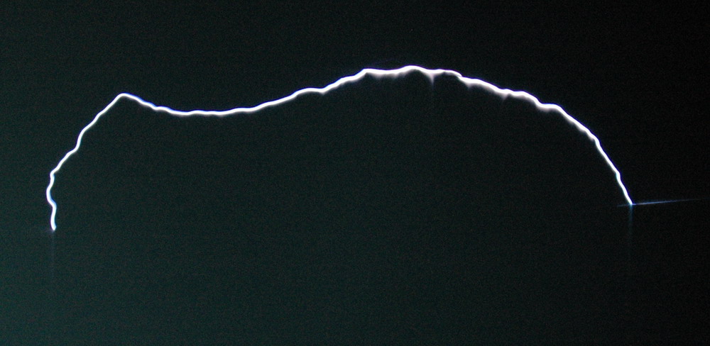
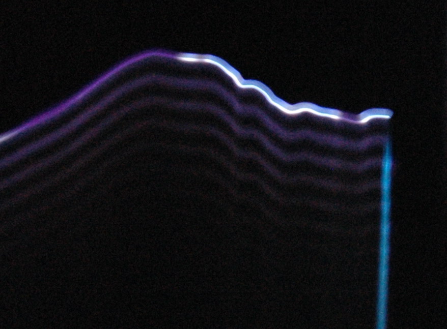
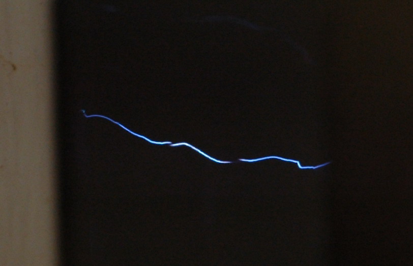
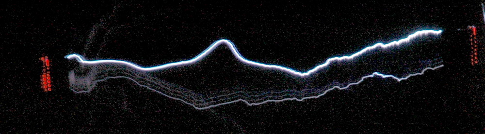
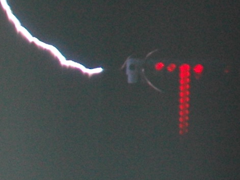
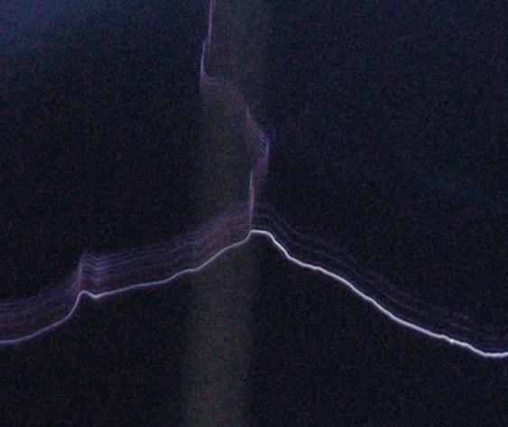
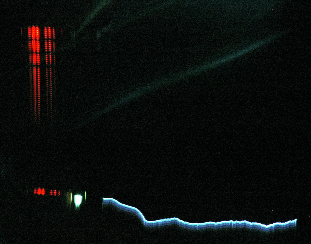
The left photo shows an arc with no following 100 kHz ring down like in the last photo. The right photo shows a bright arc with faint ring down.


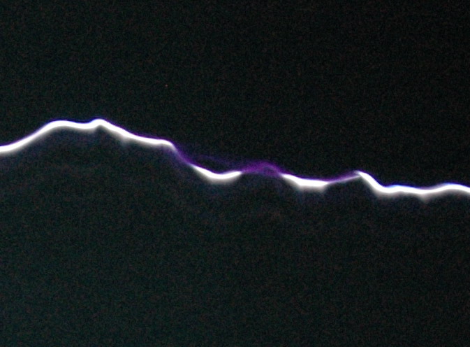
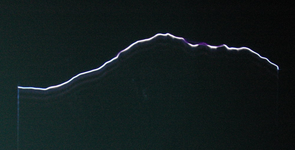
The left photo shows gaps in the bright white arc channel filled with faint purple arcs. The right photo shows detail of the initial spark which has a clear central channel on the enlarged view.


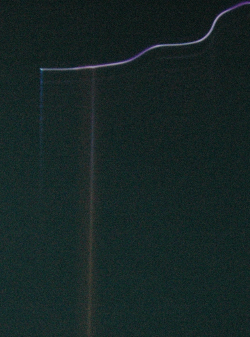
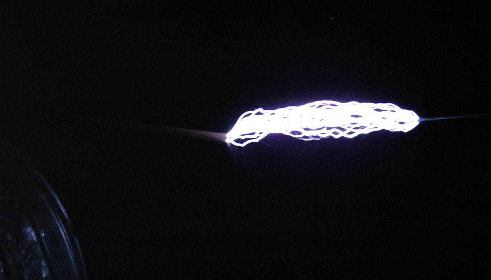
The left photo shows the ionization around the stainless steel electrode which does glow red hot at the end of a run although that is too faint to see. Thecenter photo shows that the ionization is sometimes delayed by 5 us after the initial spark strikes. The right photo shows an unusual streak that I suspect is the spark channel hitting a dust mote and burning it up.


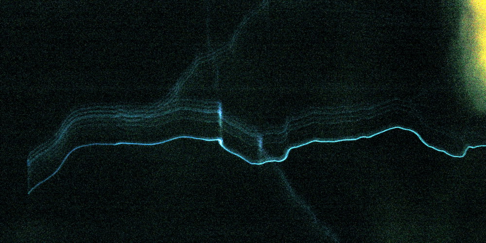
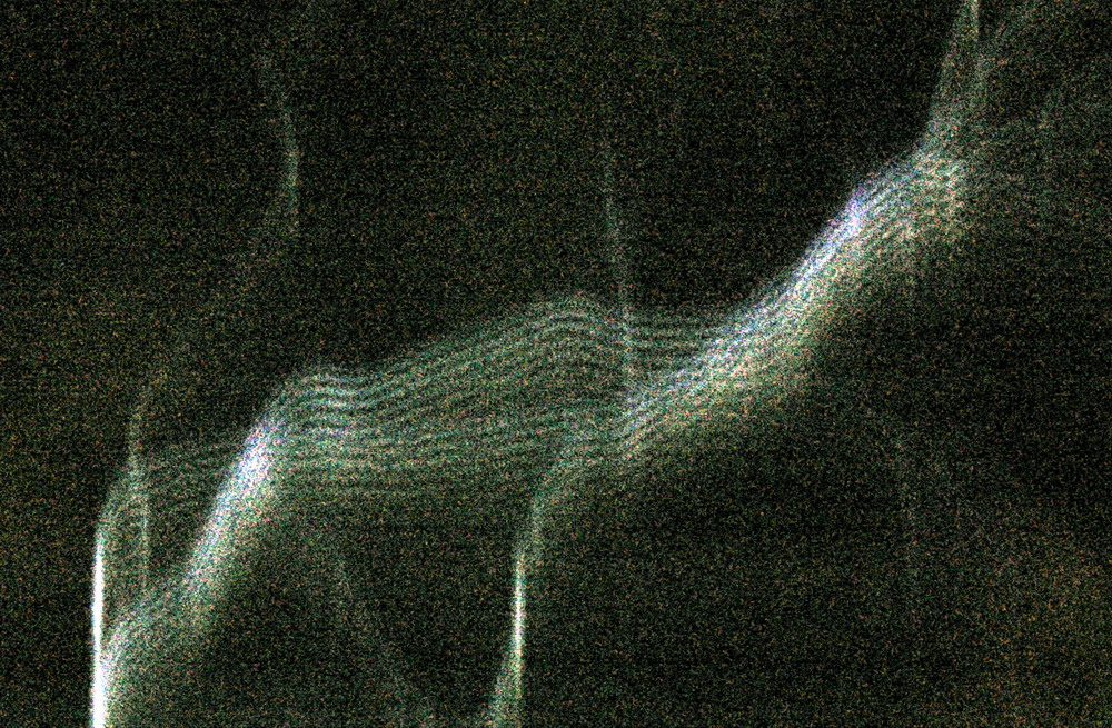
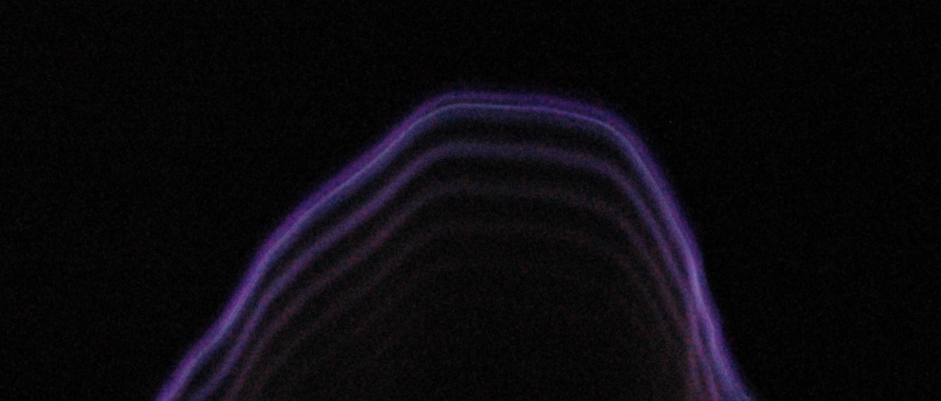
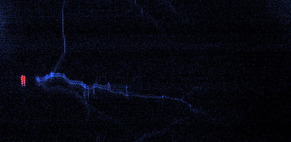
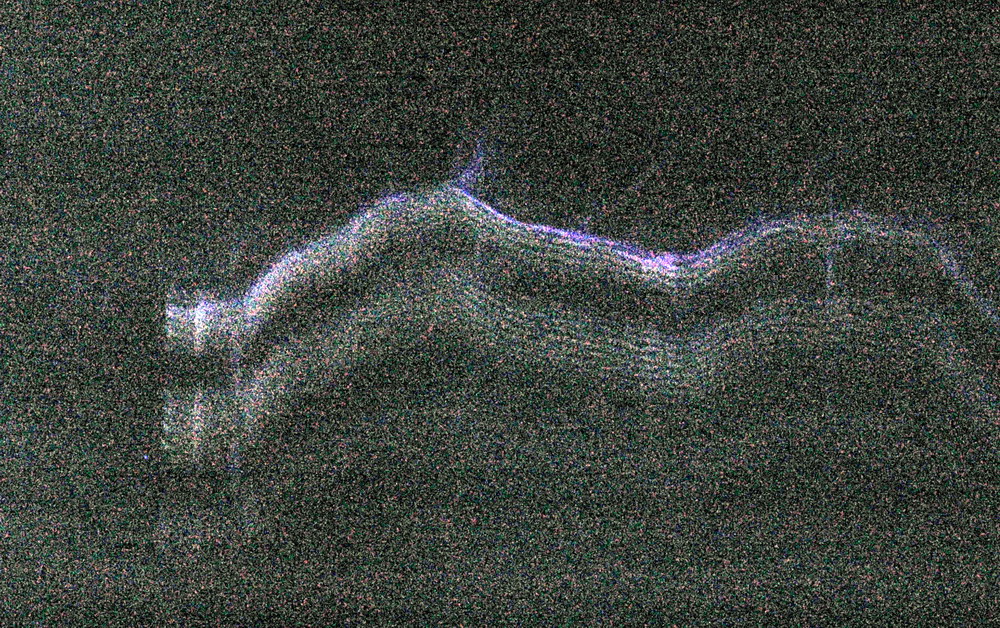
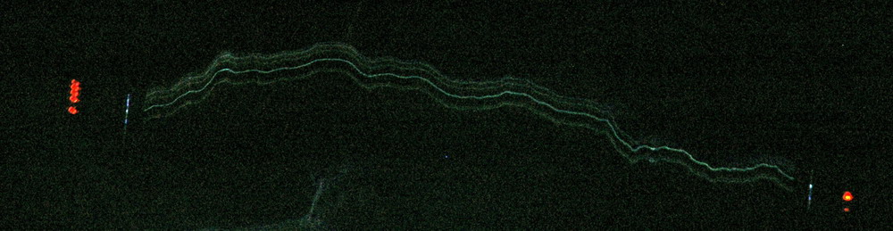
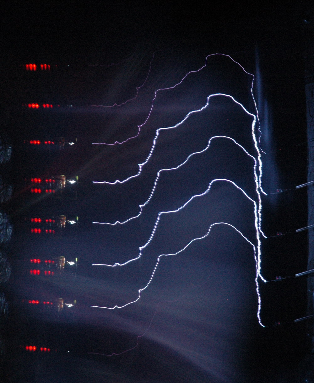
The left photo shows a streamer which is about 12 inches of an 18 inch spark from the toroid side on the left. I was throttling the variac back to try to just get streamers and few hits. It is quite different. Time axis is downward. The initial streamer sparks (the top one) can be broken into perhaps 6 consecutive channels (5us apart = 2 pulses per 100kHz). Although it is difficult to be sure, only the last one makes it across the screen then a 10us gap then the main arc hits. Interestingly there is no ring down on the main arc, however the distances are greater and intensity is down. The center photo shows two different streamers which are unrelated but overlapping. It shows the variability in intensity of subsequent spark channels and the gap before the main arc forms. Perhaps this is a harmonic effect and the spark channel is actually of greater energy than the channel before The right photo shows the streamer ring up sparks of as many as 8 sparks in a row.
I guess the new information from the rotating mirror stuff is that streamers enlarge with successive cycles and ring up leading to a spark that connects. Sparks that connect (often) have a ring down. Not really unexpected from the CRO pics but nice to see it directly. So streamers ring up and sparks ring down – easy to remember.

Photo Date: 2009

High Speed Spark Photography 1

HV Broken Sparks Rotating Mirror Tesla Single

Now this is interesting. This is taken through a rotating mirror.


I joined a first surface laser mirror to one of my motors. Running at 2250 RPM and with the spark 16 cm away the radial velocity of the spark is 37 m/s. With the image being only the negative 2 cm of a total 7 cm spark width, the vertical distance of the photo is 500 us. So you should see events in the region of 10 us easily enough. There doesn’t seem to be any structure at that level around the discontinuity.


 The Tesla coil above is my junk coil running on half of a 12 kV 30 mA NST. It has a few ceramic caps and a 3 segment static gap. Primary is 15 turns and secondary is 260 turns in 11 inches. There is usually no toroid but I used one to intensify the sparks by putting an old tin on top. The gap is only about 2 cm to all fit in the mirror view. You can just see the spark in the mirror in this photo.
Of course, with each spark lasting microseconds or less it becomes harder to catch a spark in the mirror. Even with 2 second exposures and the spark firing at perhaps 20 Hz you only get a spark in view occasionally. It should be easy to increase the resolution by a factor of 10 – 20 to see events at microsecond level. It may take many minutes of exposure to get a spark though.
This would be of great interest to Tesla coiling to get sparks seen on that time frame.
Note that this is not a true high speed photograph. Vertical movement of the spark on the image may be due to irregularity of the spark or due to events happening in time. Multiple spark channels should show up well or stepped leaders perhaps. 


The left photo shows a single spark and the centre photo shows multiple sparks captured with a longer exposure. Mirror to spark distance is 38 cm which means that the image moves at about 100 m/s. The picture represents about 2 cm width and 4 cm height i.e. vertical scale is 40 us. (just over 100 ns/pixel). The right photo shows a view of a LED being flashed at 100 kHz hence the distance between each LED is10 us.
So what do we see and how to interpret it?
There is a ladder of sparks with each spark being fairly discrete and without any obvious parallel sparks. All sparks seem complete and there are no discontinuities. Almost all sparks are bright at the ends but less bright in the centre third. This also corresponds with what you see when it is running. I am not sure what it means, however, if each spark is a single cycle then the negative one third may brighter each half cycle, leaving the centre dim.


The left photo shows a Royer ZVS circuit firing a rewound inverter MOT transformer to give perhaps 2 kV at 15 kHz. It wasn’t bright enough to show so I later added a diode, resistor and .06uF mica cap to give a brighter spark which was rather irregular due to the low firing voltage. The right photo is 100 vertical pixels = 10us showing 3 sparks of less then 1us duration, which appear to deviate from a vertical line. Going back to the setup photo, you can see that one of the electrodes is vibrating changing the spark position.
The 3 sparks suggest that there is a resonance at about 10 us period – 100 kHz due to the .06 uF cap and the effective series inductance of the cap itself plus the two 8 inch crocodile clip leads. As you can judge by the pixilation (automatically smoothed by the software) plus the noise, the camera is being pushed to the limit. Very small sparks still seem to be point events. Hopefully a 2 foot TC spark will have more structure.
To see speed of light events I would need to have 500 foot events which would be 1us. In fact it would not be too hard to bounce a laser over a path this length to show the speed of light. Hmmm… I have a corner cube prism and two eight inch parallel first surface mirrors. Add a beam splitter or two, line it all up and go. Ohh, and it needs to have picosecond switching. Did I mention that? Maybe my scanner Hex mirror assembly could rotate the laser beam to give fast enough effective switching. Head is starting to hurt here.

High Speed Spark Photography 2

The motor has a larger first surface mirror for Tesla coil photography
A larger mirror was fitted to the rotating mirror setup that allows a type of high speed photography.


This was the smaller mirror (7 cm square)  that preceded it. This is more compatible with the size of my camera and it shows the lens cap for comparison.


The left photo shows the view of a 25 inch spark with LED monitors on both toroid and ground ends with the rotating mirror stopped. The centre photoshows a negative strike from the toroid end to ground with the appropriate polarity being mirrored at the other terminal with identical ring down. It is not always like this and the toroid end in particular often has less ring down than the ground. The right photo shows a streamer with a ring up and after several rings it strikes. I am not sure if the bright spark above it is related. It is possible that a strike had a ring down but restarted as a streamer down a different channel which rung up until it struck again.


The left photo shows a streamer from the toroid and a straight streamer from the other side. Unfortunately this was a strike that bypassed my LED and went directly to the grounded ladder. It was only later that I appreciated that the three groups of LED flashes was showing a harmonic frequency influencing the output. The centre photo shows a streamer with a clear ringing which fades. The right photo shows a spark (bright horizontal) with ring down, superimposed on a diagonal streamer with a ring up.


The photo above shows the new larger mirror measuring 10 x 15 cm. This is a higher quality rear silvered mirror with no visible distortion on viewing at a distance. It is well centered but moves a fearsome amount of air and has some vibration at 3000 RPM (250 VAC) but 2000 RPM (85 VAC)seems comfortable. The reduced revs should be countered by the much clearer and wider view. Still needs to be tested in use though. It is a big mirror to spin fast but the aluminium supports seem to hold it firmly without adding too much weight or obstructing the view.
 

The left photo shows the much sharper pictures which reduce the spark to about 3 pixels width. At about 100 pixels per inch this is about .03 inch or about 1 mm. This is a daytime shot so contrast is low. The right photo shows detail which has been left pixilated showing how narrow the focus is. This is from 8 feet showing each pixel of 1/100 th inch. It also shows two parallel artifacts. I think these are from mirror stresses giving aberration from a flat surface. Alternatively, they may be internal mirror reflections from the rear silvered mirror but these should only be on one side if that was the case. Fortunately they are horizontally displaced and can be differentiated from vertical displacement with spark ring down. Now that the camera is getting a full lens view of the whole spark it should achieve close to its optimum performance. Seemed to get worse during the day so needs a new design with no stress and epoxied in place. This was a daytime shot and in retrospect was probably sharper than the night shots as it was f18 and 1/10 sec. Night shots were f3.5 and longer duration. Possibly a proper optically flat first surface is needed.
At a motor speed of 2160 RPM and camera distance of 8 feet, the scan speed is 900 feet per second = 300 m/s. This is around 1,000,000 pixels per second. So 1 pixel per microsecond which is a nice round figure. Hence the ring down sparks should be 5 pixels apart at 200 kHz per half cycle which is 10 times slower than some of the photos above. However this is with a full 2 foot spark in view. If I change lenses and distances this can be spread out much further but I could not fit the full 2 feet width in view.


The left photo shows the negative LED firing well and repeatedly, but I guess this was due to some asymmetry in the LED’s as it seems to be happening on one day. Makes you wonder though as I was using slow rotary spark gap (ARSG) rates today. The alternative explanation is of another harmonic frequency being involved. The right photo shows a current meter but I have had problems with it. Possibly overvolting the metal film 1/8 W resistors. Certainly looks like one resistor is open circuit here. They should fire at 0.01, 0.1, 1 and 10 amps respectively left to right but the 1 amp LED is firing too readily. The 100 A and above LED’s never fired. (but did with a capacitor on a rectified ignition coil setup).


The left photo shows a second and possibly third group of streamers following. The right photo shows the addition of a spark arrestor and a disposable camera xenon flash in series with unprotected LED’s. I got this interesting but blurred streamer shot showing a remarkable 6 streamer groups that the camera and LED’s weren’t picking up. Seems like there is a another frequency superimposed of perhaps 8-10 kHz. I presume that this is the difference between primary and secondary resonances (the “notch”). I am running the Tesla coil a bit out of tune still so that may account for that. It could actually explain a row of negative only ring down sparks as well.
I think the spark gap arrestor is the most sensitive at picking up streamer currents and is more of a point source than the Xenon.


The left photo shows a streamer branch with only alternate streamers progressing from left to right after the branch. This suggests some polarity effect at the time e.g. negative goes to the upright branch and positive continues on. The right photo shows detail of a streamer that connects during the time when the harmonic is resulting in low voltages, hence the current is low and the spark is not strong. As the voltage picks up, there is enough energy for a second strike. The left LED’s are not functioning properly but do indicate the first group of firings then a gap and then a second lot starting. I also have the spark arrestor running here which is the blue streak between the LED’s and the spark.


The left photo shows a 4 foot streamer branch and multiple spark views. The right photo also shows multiple views of a 3 foot spark burning up the resistor to the LED’s.


The left photo shows the second version of the current meter. Just regard it as a sensitive single indicator LED at present. A spark recorded relatively brief activity only but a nearly invisible streamer gave a prolonged ring. I did wonder if this was due to ringing from the 1 MHz low pass filter but in other shots the Xenon is firing for a good proportion of these so that resonance seems unlikely. The ring frequency of the filter should be ten times faster in any event. The right photo shows the Xenon (blue region on right) firing for the first three groups.


 The photo above shows a view with the motor running at a slow 200 RPM (instead of 2000 RPM). It shows the sequence of strikes down the same channel. Spacing between sparks is about 1.5 ms which corresponds to about 600 Hz which is about right for my spark gap at about half speed. What you are seeing therefore is sparks rising in one half cycle of 50 Hz mains with the intensity increasing and then decreasing.
Terry Fritz has done a lot of work on streak cameras as well with excellent results. His pictures and the race to develop this is detailed in this thread in the 4HV forum.