A larger mirror was fitted to the rotating mirror setup that allows a type of high speed photography.
This was the smaller mirror (7 cm square) that preceded it. This is more compatible with the size of my camera and it shows the lens cap for comparison.
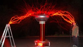
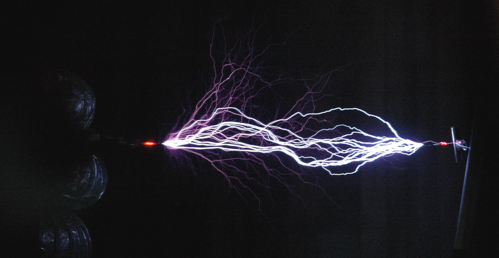
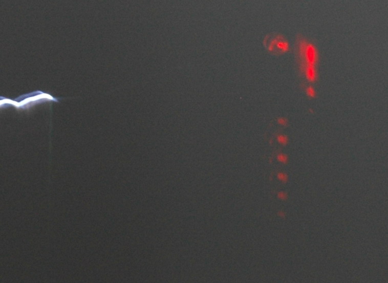
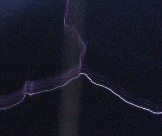
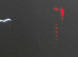
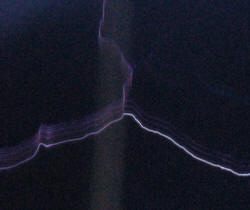
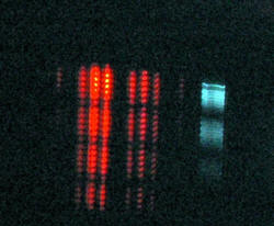
The left photo shows the view of a 25 inch spark with LED monitors on both toroid and ground ends with the rotating mirror stopped. The centre photoshows a negative strike from the toroid end to ground with the appropriate polarity being mirrored at the other terminal with identical ring down. It is not always like this and the toroid end in particular often has less ring down than the ground. The right photo shows a streamer with a ring up and after several rings it strikes. I am not sure if the bright spark above it is related. It is possible that a strike had a ring down but restarted as a streamer down a different channel which rung up until it struck again.
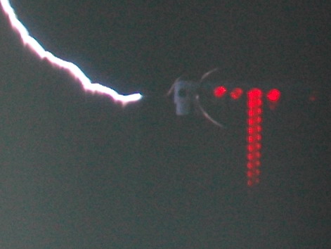
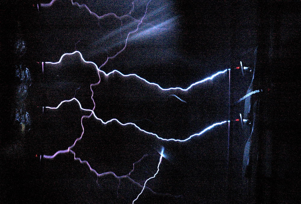
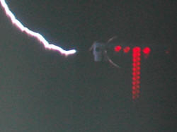
The left photo shows a streamer from the toroid and a straight streamer from the other side. Unfortunately this was a strike that bypassed my LED and went directly to the grounded ladder. It was only later that I appreciated that the three groups of LED flashes was showing a harmonic frequency influencing the output. The centre photo shows a streamer with a clear ringing which fades. The right photo shows a spark (bright horizontal) with ring down, superimposed on a diagonal streamer with a ring up.
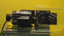
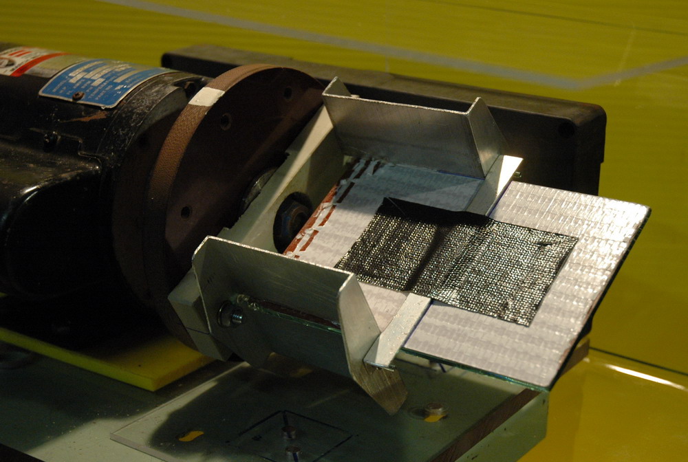
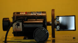
The photo above shows the new larger mirror measuring 10 x 15 cm. This is a higher quality rear silvered mirror with no visible distortion on viewing at a distance. It is well centered but moves a fearsome amount of air and has some vibration at 3000 RPM (250 VAC) but 2000 RPM (85 VAC)seems comfortable. The reduced revs should be countered by the much clearer and wider view. Still needs to be tested in use though. It is a big mirror to spin fast but the aluminium supports seem to hold it firmly without adding too much weight or obstructing the view.
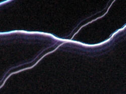
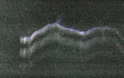
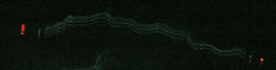
The left photo shows the much sharper pictures which reduce the spark to about 3 pixels width. At about 100 pixels per inch this is about .03 inch or about 1 mm. This is a daytime shot so contrast is low. The right photo shows detail which has been left pixilated showing how narrow the focus is. This is from 8 feet showing each pixel of 1/100 th inch. It also shows two parallel artifacts. I think these are from mirror stresses giving aberration from a flat surface. Alternatively, they may be internal mirror reflections from the rear silvered mirror but these should only be on one side if that was the case. Fortunately they are horizontally displaced and can be differentiated from vertical displacement with spark ring down. Now that the camera is getting a full lens view of the whole spark it should achieve close to its optimum performance. Seemed to get worse during the day so needs a new design with no stress and epoxied in place. This was a daytime shot and in retrospect was probably sharper than the night shots as it was f18 and 1/10 sec. Night shots were f3.5 and longer duration. Possibly a proper optically flat first surface is needed.
At a motor speed of 2160 RPM and camera distance of 8 feet, the scan speed is 900 feet per second = 300 m/s. This is around 1,000,000 pixels per second. So 1 pixel per microsecond which is a nice round figure. Hence the ring down sparks should be 5 pixels apart at 200 kHz per half cycle which is 10 times slower than some of the photos above. However this is with a full 2 foot spark in view. If I change lenses and distances this can be spread out much further but I could not fit the full 2 feet width in view.
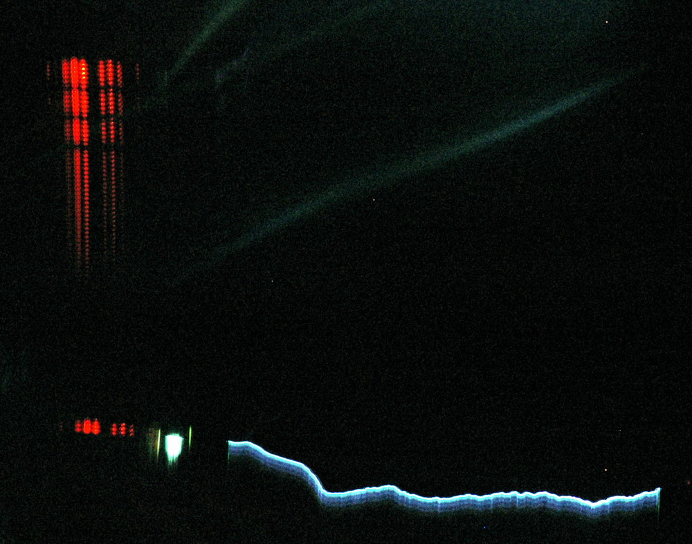
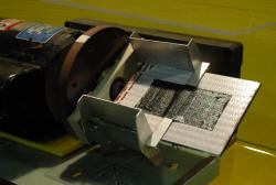
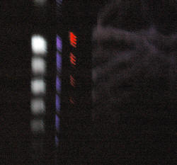
The left photo shows the negative LED firing well and repeatedly, but I guess this was due to some asymmetry in the LED’s as it seems to be happening on one day. Makes you wonder though as I was using slow rotary spark gap (ARSG) rates today. The alternative explanation is of another harmonic frequency being involved. The right photo shows a current meter but I have had problems with it. Possibly overvolting the metal film 1/8 W resistors. Certainly looks like one resistor is open circuit here. They should fire at 0.01, 0.1, 1 and 10 amps respectively left to right but the 1 amp LED is firing too readily. The 100 A and above LED’s never fired. (but did with a capacitor on a rectified ignition coil setup).
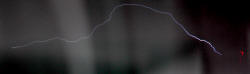
The left photo shows a second and possibly third group of streamers following. The right photo shows the addition of a spark arrestor and a disposable camera xenon flash in series with unprotected LED’s. I got this interesting but blurred streamer shot showing a remarkable 6 streamer groups that the camera and LED’s weren’t picking up. Seems like there is a another frequency superimposed of perhaps 8-10 kHz. I presume that this is the difference between primary and secondary resonances (the “notch”). I am running the Tesla coil a bit out of tune still so that may account for that. It could actually explain a row of negative only ring down sparks as well.
I think the spark gap arrestor is the most sensitive at picking up streamer currents and is more of a point source than the Xenon.
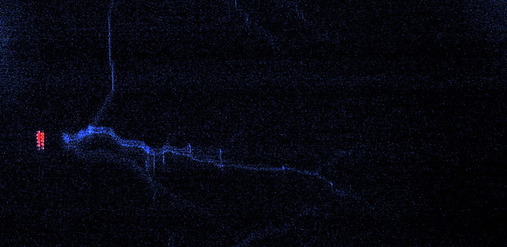
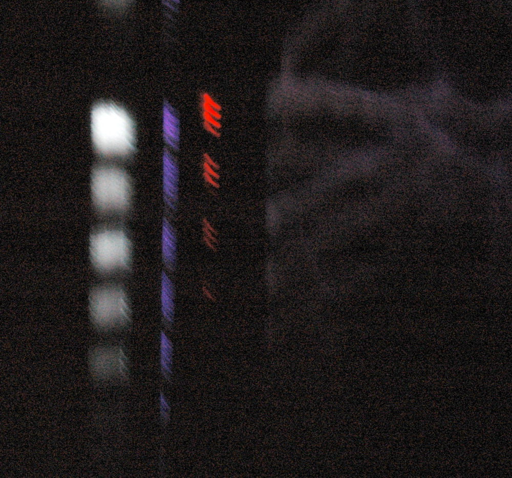
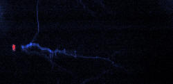
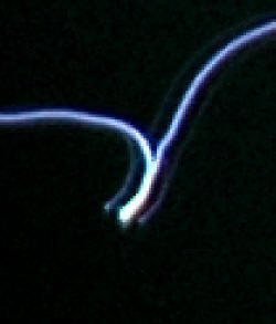
The left photo shows a streamer branch with only alternate streamers progressing from left to right after the branch. This suggests some polarity effect at the time e.g. negative goes to the upright branch and positive continues on. The right photo shows detail of a streamer that connects during the time when the harmonic is resulting in low voltages, hence the current is low and the spark is not strong. As the voltage picks up, there is enough energy for a second strike. The left LED’s are not functioning properly but do indicate the first group of firings then a gap and then a second lot starting. I also have the spark arrestor running here which is the blue streak between the LED’s and the spark.

The left photo shows a 4 foot streamer branch and multiple spark views. The right photo also shows multiple views of a 3 foot spark burning up the resistor to the LED’s.
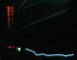
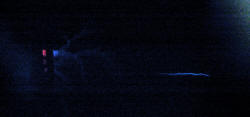
The left photo shows the second version of the current meter. Just regard it as a sensitive single indicator LED at present. A spark recorded relatively brief activity only but a nearly invisible streamer gave a prolonged ring. I did wonder if this was due to ringing from the 1 MHz low pass filter but in other shots the Xenon is firing for a good proportion of these so that resonance seems unlikely. The ring frequency of the filter should be ten times faster in any event. The right photo shows the Xenon (blue region on right) firing for the first three groups.
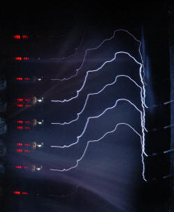
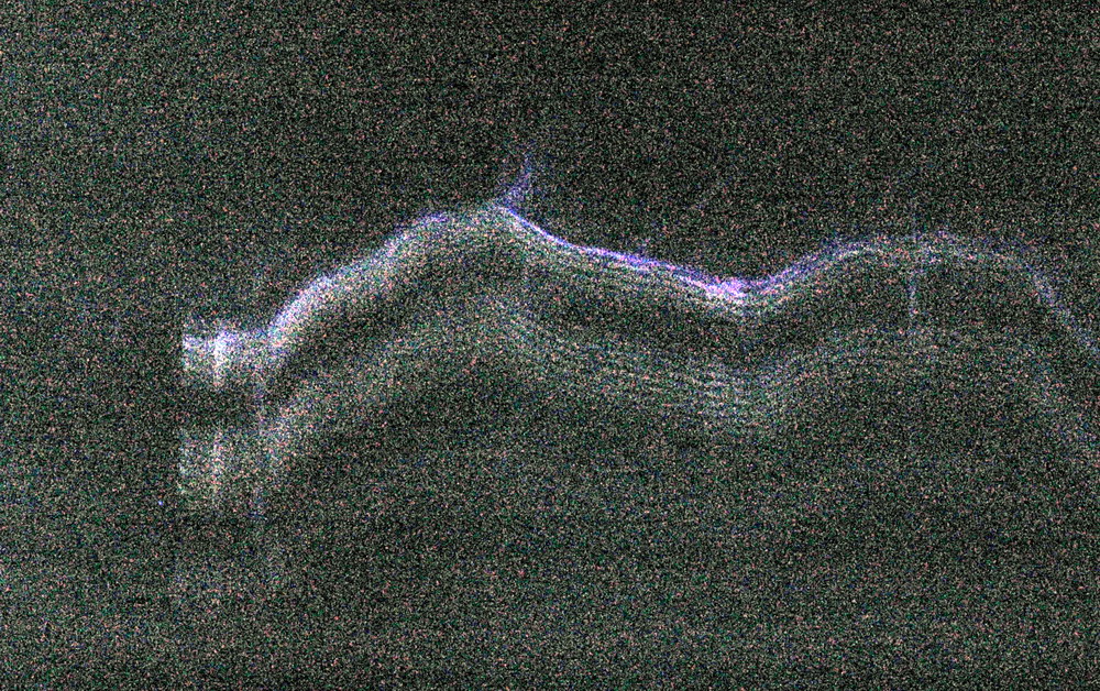
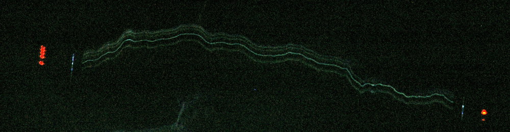
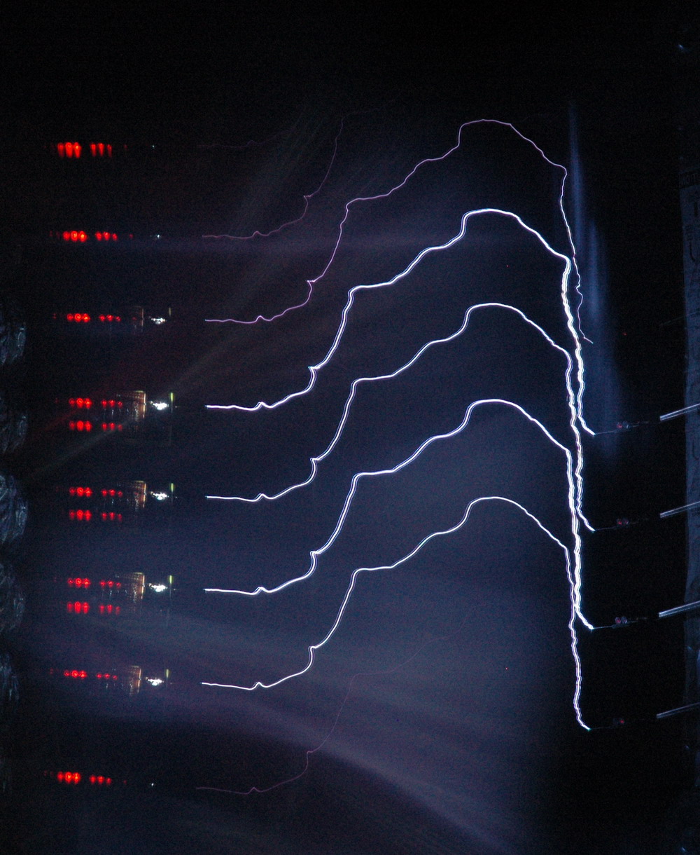
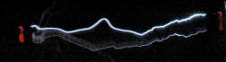
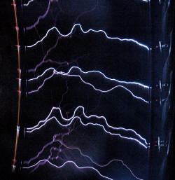
The photo above shows a view with the motor running at a slow 200 RPM (instead of 2000 RPM). It shows the sequence of strikes down the same channel. Spacing between sparks is about 1.5 ms which corresponds to about 600 Hz which is about right for my spark gap at about half speed. What you are seeing therefore is sparks rising in one half cycle of 50 Hz mains with the intensity increasing and then decreasing.
Terry Fritz has done a lot of work on streak cameras as well with excellent results. His pictures and the race to develop this is detailed in this thread in the 4HV forum.