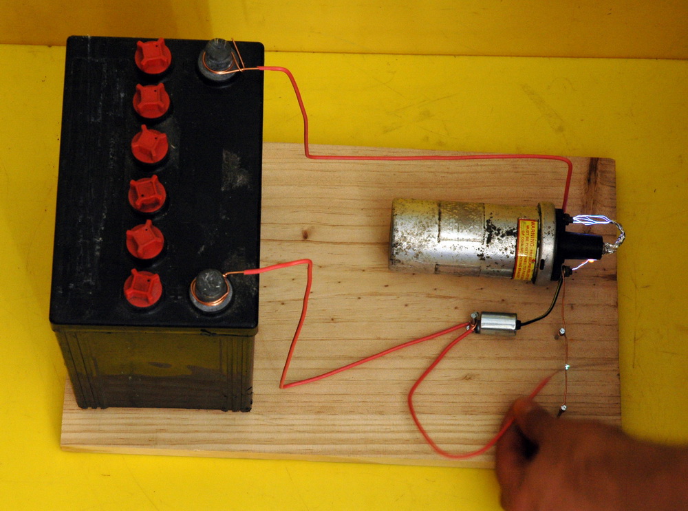
 Here is a fast, cheap and generally safe project for beginners sparks with a minimum component count. It uses an ignition coil from a car.
“Continue reading” for more details and photos.
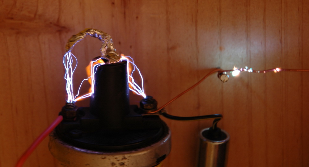
The 3 second photographic exposure above shows 1 inch sparks from this project. Here’s what you need.
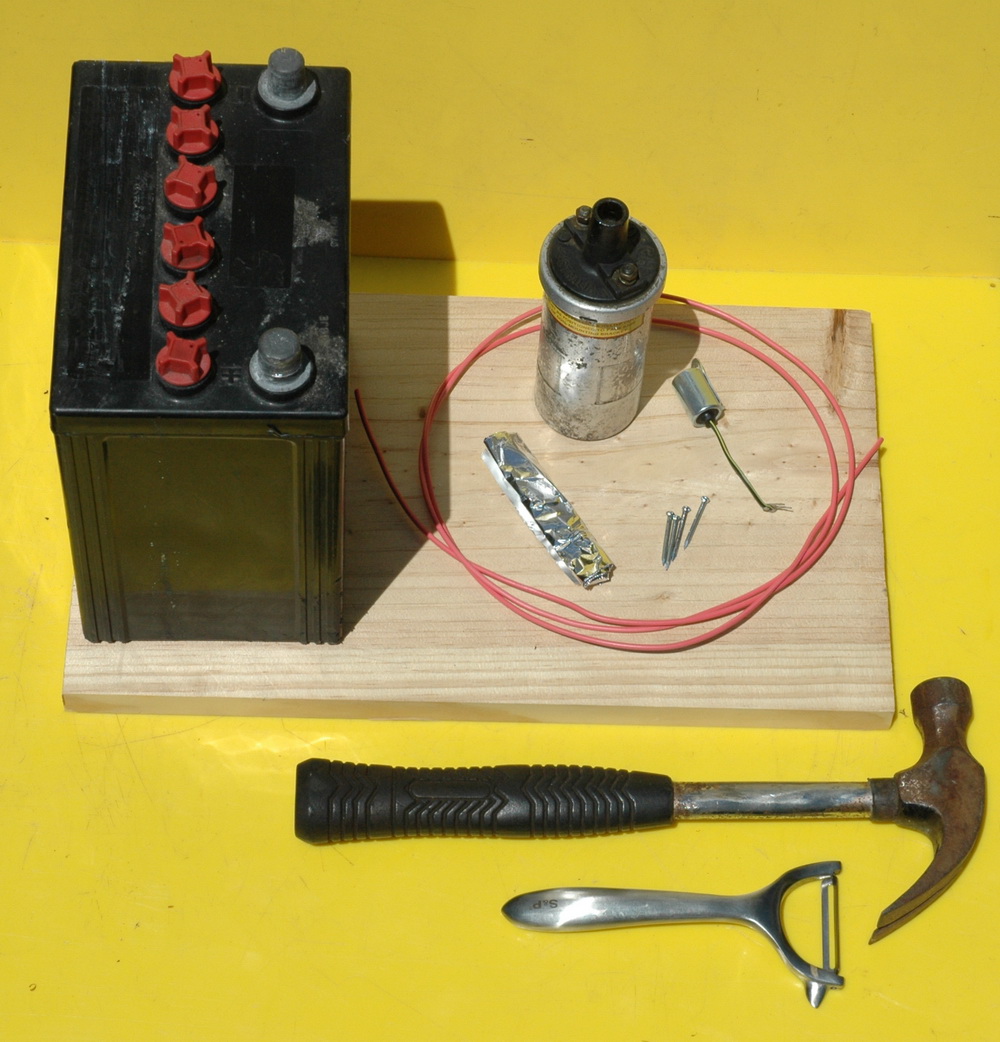
Parts
1: Car battery
This is simplest and safest but a battery charger might do or a 12 V sealed lead acid (SLA) battery. It will draw about 12 amps with a fully charged battery. The battery should be removed from the car to avoid any risk to its electronics. Maybe ask a battery place or service station for a recently “dead” battery that has a bit of charge in it. They should still provide 12 amps but not a cranking 100+ amps. Ask if you can bring it back for disposal as they are not suitable for domestic rubbish.
2: Ignition coil
This can be obtained from car wreckers for a few dollars. The “can” type was used extensively in pre 1980’s cars and is one part of the Kettering ignition system that this project is based on.
3: Condenser
This is the 1 inch long cylinder with a black wire coming out of it above. This is a part found in the distributor of cars of that era. I bought one new for $13 as the wreckers wouldn’t split it from an old $30 distributor. A condenser is an old fashioned name that the auto trade uses for a capacitor with a typical value of 0.22 uF (microFarads). You could substitute a capacitor from your local electronics store rated at 200 V or more with a capacitance of 0.22 up to 1.0 uF which would be cheaper or just experiment. A “greencap” or similar polyester type capacitor seems suitable.
4: Wire
A few feet of almost any type of wire that you can strip the insulation off. Here I have used single strand wire which strips simply with a potato peeler (or use a pocket knife).
5: A few nails
Nails can be of almost any size. Wood screws would do fine too.
6: A small piece of aluminium foil.
This is just to stuff down the top of the ignition coil to reach the contact about one inch down the insulator.
7: Wood
The base can be anything you can nail into. Chipboard or laminates are fine
Instructions:
Wind the wire to the various points by just winding a number of turns of the bared wire around each nail or terminal. Do the battery terminal last because this makes it “live”.
Stuff some scrunched up foil down the inside of the black insulator to touch the contact at the bottom.
The wiring layout:
The switch (equivalent of the “points” in an ignition system) is the two wires at bottom right. One between the nails and bare and the other is free and not connected.
To operate:
Very briefly touch the two wires together. You should see a very small spark where the wires touch. Current is now flowing into the coil and has built up an internal magnetic field. Immediately lift the wire off to break the contact. The collapsing field creates a voltage spike of hundreds of volts which is raised to perhaps 30,000 volts at the output. You will see another spark where the wires were touching, larger this time. In most cases you will see a long high voltage spark from the aluminium foil to one of the terminals. The right photo show a 2 second exposure with several long sparks. So you have completed it and have made some sparks. But is it safe? Yes and no. A shock from this to is similar to being pricked with a needle. Not pleasant but tolerable. Of course if you jump backward and trip over and hit your head then yes you may do some injury.
Caution:
The one thing you should NOT do is to leave the wires in contact. The current draw will be high, wires will melt and the coil will overheat. Quickly scraping them across is fine.
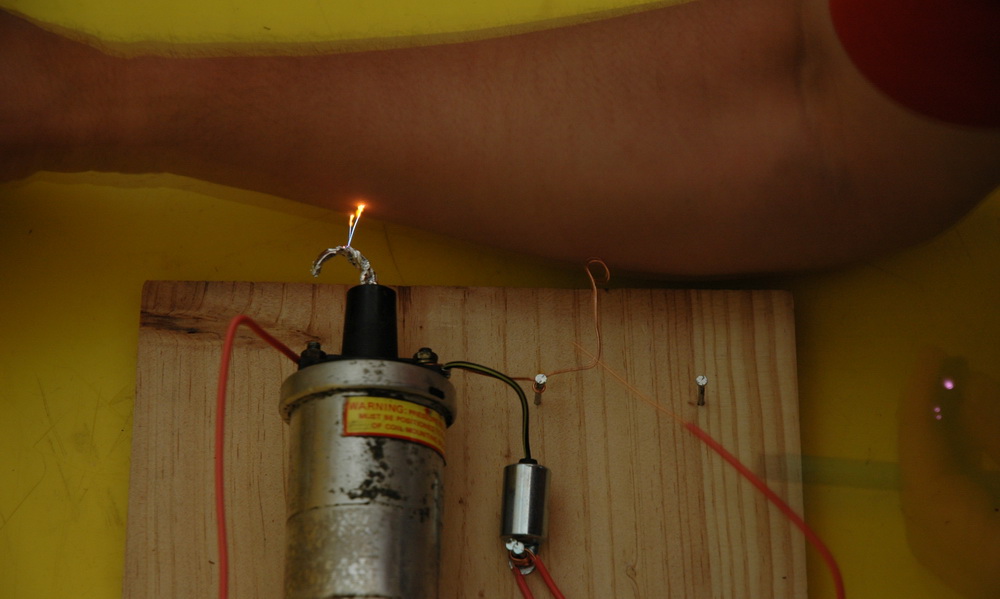
Here is a spark onto my arm. I had to turn on the camera remote and turn on the sparks with my left hand, seen only as a blur in this 2 second exposure. It took about 10 shocks to get a reasonable picture. My right arm receiving the shock will jump involuntarily. That’s how muscles work and was discovered by Galvani giving shocks to frog legs. Anyway, I survived unscathed although I probably get more practice than most. So what can you do with it?
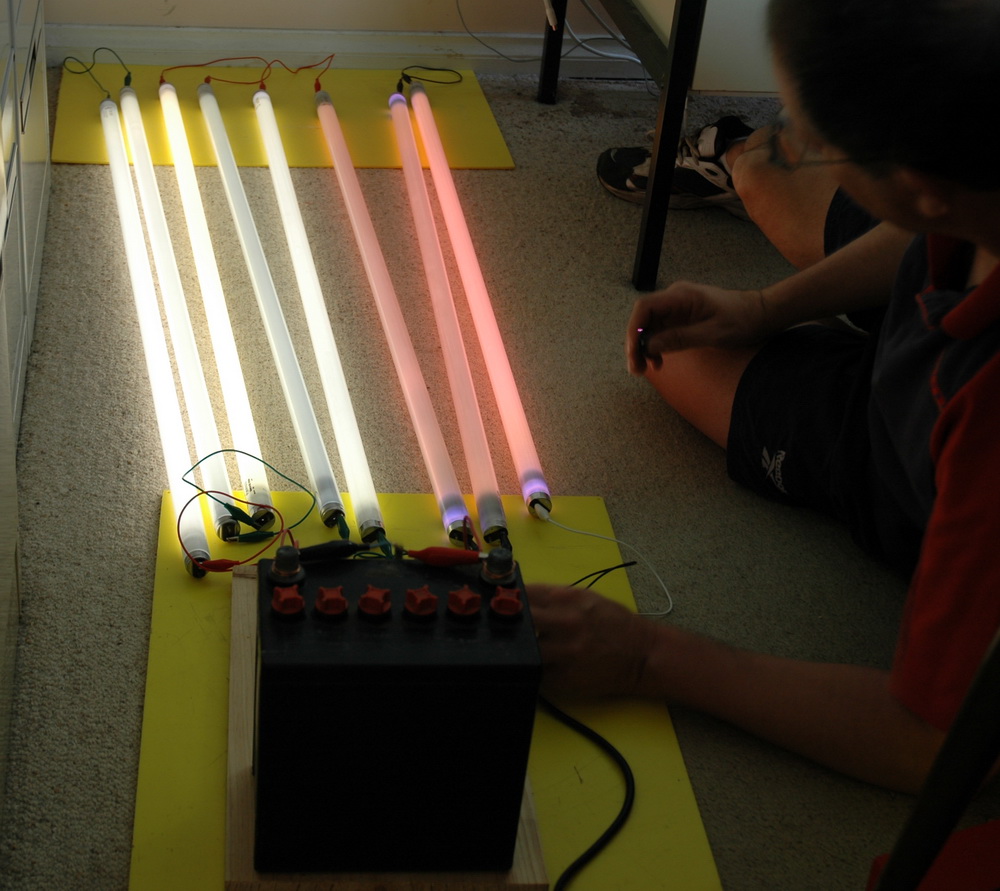
How about lighting up a lot of “dead” fluorescent lights? As you can see, some are more dead than others. Try testing conductivity of various objects like dry then wet wood or plastic. See how well it jumps through paper or thin plastic. Just a note. High voltage can damage electronic equipment like phones, iPods, TV’s and computers. Keep them well away. 30,000 volts will jump 1 inch and 2-3 inches along the surface of insulation.
How it works:
Touching the wires will cause energy to be stored in a magnetic field in the ignition coil.
Removing the power makes the field collapse which creates a voltage spike of hundreds of volts in the primary of the ignition coil. This induces a large voltage of perhaps 30,000 volts at the output.
The condensor allows this collapsing field energy to pass back to the other terminal of the primary coil via the battery. This allows a resonance to occur and the energy to be sustained.
Relay driven ignition coil beginners sparks
If you want to progress further to something a little more complicated, try this: It uses a relay as a vibrator to turn current on and off rapidly to an ignition coil.
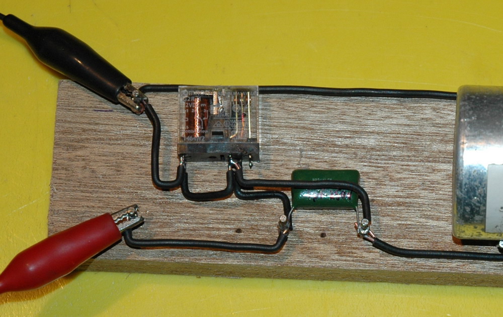
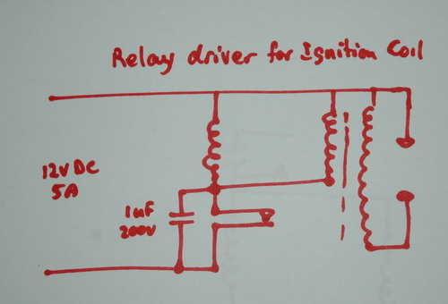
The top photo shows the ignition coil and relay running on 12 volts at 5 amps from a power supply, battery charger or car battery. There are only three parts. It uses a relay as a vibrator to turn current on and off rapidly to an ignition coil. The middle photo shows a close up of the wiring. The bottom photo shows the schematic with the capacitor, relay and ignition coil.
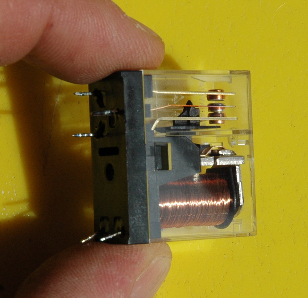 This photo above shows the relay with the connection for the coil as the bottom two pins and the other contacts coming out in line. Note the centre contact is the one that moves and touches the lower contact in this picture. This is the “normally connected” (NC) pole and is the one used here. The top contact is the “normally open” (NO) pole and is not used.
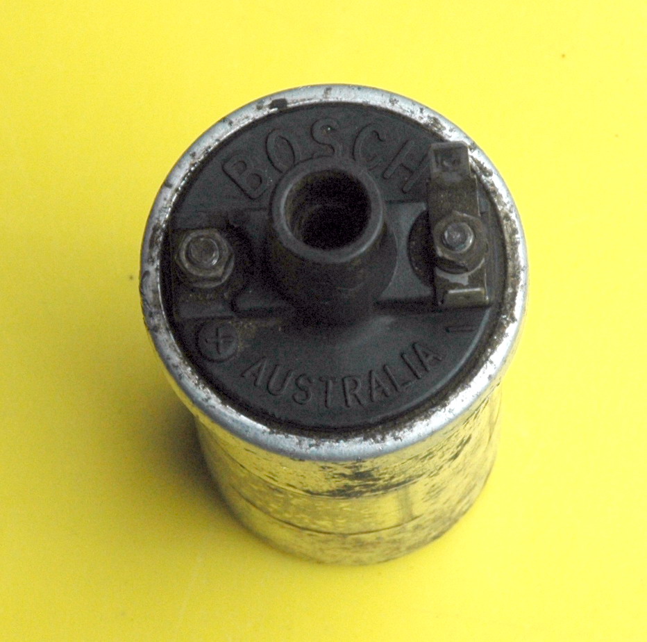
This photo shows the ignition coil close up. Relay lifetime will be limited and the contacts will burn out before too long.
I often get people with little experience wanting to make a Tesla coil as a first HV project. Perhaps school kids looking to do a science fair project. I have been very reluctant to encourage Tesla coil building in that age group in view of the lethal nature of the supply. I’ve often had to point them off to other sites for simple HV projects. This has been the motivation behind this little project. In fact it was the way I got into HV when I was 14 and I used a multivibrator out of a valve radio set to run two IC’s. It is pretty safe and lots to learn and do with nothing really critical.
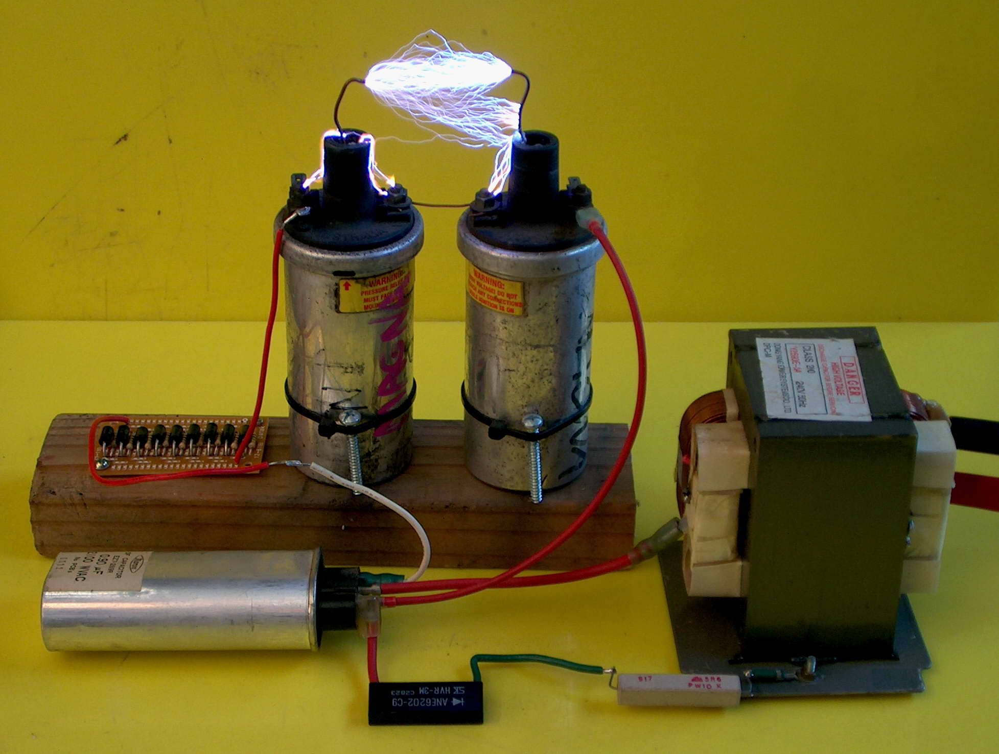
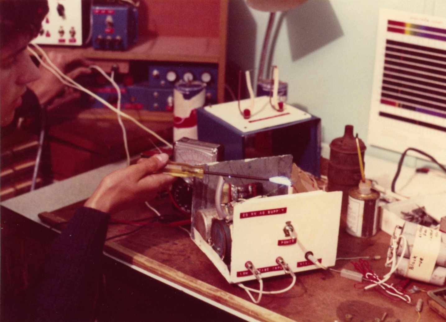 High voltage 1972 style with twin ignition coils using the identical circuit running 2 coils.
Related pages
Try something else
External links
Photo Date: 1972, Oct 25, 2006


 Ignition coils
 FAQ
FAQ