Category Archives: High Voltage

Look, don’t touch. I love high voltage. There, I’ve said it. Lots of different ways to make it apart from rubbing your shoes on carpet. Here we explore the making of high voltage and the art of the resulting images.

Can Crusher 2

Crushing Red Bull cans at different energies

Can Crusher 2 reaches a power able to tear the can in half. This one uses a third high voltage 500 joule medical defibrillation capacitor. This makes a total of 1500 joules and with straight and shortened wiring paths this model performs much better.
“Continue reading” for more details and photos.  Continue reading

Can Crusher 4

Can Crusher 5kJ Can Crusher 4 using a pulse capacitor bank rated up to 10 kJ. Time to get serious! My big caps have arrived. Total stored energy with all charged to capacity is 10 + 10 + 8 = 28 kJ.
“Continue reading” for more details and photos.
Continue reading

Gallery of Sparks

HV Eye Single Bright

Here are some of the highlights of high voltage spark photos. For a gallery of Tesla sparks go to Tesla sparks.


Above left photo shows a 5 inch (12 cm) arc from a mobile x-ray supply. It is DC about 100 kV with a large capacitor but goes through a large HV resistor within the white tube. There is a large convoluted power arc that last about 1/2 second. The right photo shows a 26 inch arc from another larger x-ray transformer running about 40 kV. It only jumps just over an inch but like a Jacobs ladder just grew and kept rising.
Alternatively one can use SIDAC’s. This very simple circuit uses the transformer, capacitor and diode out of a microwave oven to supply 2000 VDC. Once the voltage rises to 2000 V the SIDAC’s fire dumping the energy into two ignition coils to give sparks of easily 5 cm. I am using 9 SIDAC’s each rated at 240 V 1 A RMS and 20 A pulse. Each is shunted with a 1 Mohm resistor to give more even voltage division. There is a 10 Kohm 10 W resistor used for these shots but power draw is triggering a 10A cutout and there is sufficient heating of resistor, diode and SIDAC’s to only allow short runs. 50 Kohm will allow about 4 sparks per second.


Unfortunately this is very hard on the ignition coil’s insulation. I have lost one coil but the remaining one still puts out 3 inches and also about 10 inches of surface tracking (below).


MOT supply in a MO. (Microwave oven transformer) 2004


The sparks when viewed end on are interesting. Or even when viewed close up….


The left photo with the safety glasses was to get the reflection. My normal glasses have an efficient anti reflection filter. The right photo was a lot harder to arrange than I thought. To get a close up of a face and sparks in one shot with a reflection in an eye means a long exposure and F stop backed off all the way to 32. Almost a pinhole camera. The virtual distance of the reflected spark is so far away that it will be really out of focus and also so much smaller and fainter due to the convexity of the eyeball. So it meant a lot of sparks to get a blue blur on the corneal reflection. Without the reflection it looks photoshopped. I have to hold my eye open and be absolutely still for 10 seconds while loud IC sparks fire off in front of my line of vision.

The set up to have sparks in front of my eye. Having the spark closer is helpful but you can’t get a 2 inch spark closer than 2 inches to your nose. I was also a little worried about cumulative UV exposure to my eye with the many takes.


This is a standard screwdriver. It is interesting how the arc bends around it. This is because the hot arc channel is a low resistance but the air just next to the screwdriver is cold (or at least not not ionised and would have to be “jumped” by a sufficient voltage for it to connect. This only happens with stable pulsed DC or AC arcs. One could make up a bit of a pseudo-explanation for this and indeed I have on the 4HV community.

Related pages

External links

Try something else

Photo Date


High Voltage Halo Effects

HV Rotating Crown Yellow Stainless Steel ball

High voltage halo effects are done with a long exposure of a rotating spark with a colour filter.

Here are some of the effects that are produced by long exposures in a similar manner to the Eye of Sauron effect but not using a Tesla coil.

The photo above shows the “Sombrero” . Well it was meant to be a crown really. Note the reflection in the stainless steel ball which shows the sombrero as well as the flash and my wife and son operating the equipment.
Note that as in all my photos there is no “photoshopping”. The pictures are all single shots and effects are produced with long exposures. Here’s how this one is done:

HV Rotating Crown 60 kV SupplyThe HV supply I wired to a rotating setup that holds the electrodes.
HV Rotating Crown Polystyrene BallThe electrodes which will rotate around the ball (or my head) and on a long exposure with appropriate orange filter which is removed before a flash to give “normal” lighting for my head.

High Voltage Halo effect with a soft flame like arcThe photo above shows the effect off a higher current changing the bright sparks into a flaming arc. I should add that the whole sensation is a bit strange. The ionic wind and charge accumulation on my hair means I can feel exactly where the electrode is.

HV Electric Kris with halo of sparksThe photo above shows an ‘electric kris’. The kris is an Indonesian curved dagger.

arthsepa

 Related pages

High Voltage Antivirus for PC and MAC  HV Antivirus

Try something else

Aerogel

External links

Kris Of Lightning My Google plus post
Indonesian curved dagger

Photo Date: March 29, 2008

Strange High Voltage Water Surface Effects

Water Arc 4 Green Striated 2

Pass a lot of high voltage DC current onto deionised water and you get remarkable colourful patterns at the water surface.

                          
 As the deionised water became conductive enough to sustain a higher current , the faint and feeble spark increased to a power arc to water of about 2 kV DC eventually to the point of making the wire red hot. The first 3 photos all show interesting variation in the surface effects. The green glow is the copper from a hotter arc.

A spark playing over a magnet submerged in deionised water.

Also of interest:
A
Next topic:
A
Next Random topic:
A
Internal Links related:
A
External:
A Wiki
A Google+ post:
A 4HV post
Photo Date: 2005, 2006, 2007

LED Polarity, Current Indicator

LED spark polarity indicator

The left photo shows the spark with some red lights on the right. These indicate polarity and the LED closest to the spark indicates a negative discharge from the toroid on the left. Next the right LED lights up with the positive cycle and so on. This shows polarity for more cycles than the eye can readily see from the photo. The center photo shows detail of the LED’s. The right photo shows the same photo as the center one but with a full view also with a negative leader.

The photo above shows the red LED’s in circuit. The spark goes directly to one end and the other end is grounded. There are two 10 ohm resistors and the LED’s are connected in parallel but with opposite polarity. These values are determined by experiment and are strange but it works. For example you can’t light the LED’s with DC unless you put in 0.4 A which dissipates 4 W and burns up the resistor which has a 1 W rating. The LED’s are bright in action and since they are turned on for only a few microseconds at a time in with a low overall duty cycle, must have a very high output during this time.

The left photo above shows a single LED being remarkably tolerant to high voltage impulses. The center photo shows the circuit diagram of the current meter and the right photo shows it in action with ignition coil sparks. The current range is a nominal .002 A to 20A and has a reverse LED as well.
All this is hard on LED’s which don’t last long. LED’s can die by degrees as below.

The left photo above shows a normal red LED driven by 6 VAC via a 1 k resistor plus antiparallel green and blue LEDs which is my wired test setup (very handy). Note the LED die (light emitting square in the centre of the LED. Only the blue LED lights as current only passes in one direction. The centre photo shows a partially dead LED where the square die has a non functioning area. In addition the LED is not bright and it conducts in both directions as both green and blue LED’s light up. The right photo shows a partially dead LED where the square die is still normal but the LED is not bright and it also conducts in both directions as both green and blue LED’s light up.
This is the second reincarnation of the current meter.

The left photo above shows the circuit diagram. Xenon light is first in series because I thought that would be most sensitive. The main current path is through a 2W 10 ohm resistor shunted by a neon. What I want to do is to remove the nastiness of the spikes then use a 1MHz low pass filter with windings on a ferrite core and a ceramic cap. After that a TVS should be able to work to limit voltages to +/- 30V and the LED’s will do the rest. The LED array should read in decades but I probably should put individual shunt resistors rather than an overall one. This needs to be redesigned as it won’t work as intended and I need to give this some more thought. The centre photo shows the xenon in action with the lights in the same horizontal line. The right photo shows the rear view with the mostly covered neon on the left and two indicator diodes on the right which should be running within ratings and shouldn’t blow but won’t be very bright either.

Future Plans (for deletion)

Future Plans


Can you work out what these have to do with high voltage or magnetism? Left, center or right for the answers.

More strange behavior of high voltage. Electrostatic levitation of non conductive (deionised) water and arcs onto a water surface.


Above left shows the 800 amp spotwelder flash. Centre is the flyback supply. Right is a battery operated Candy box HVsupply using old camera and TV parts.

Spark Structure

Broken sparks

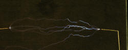
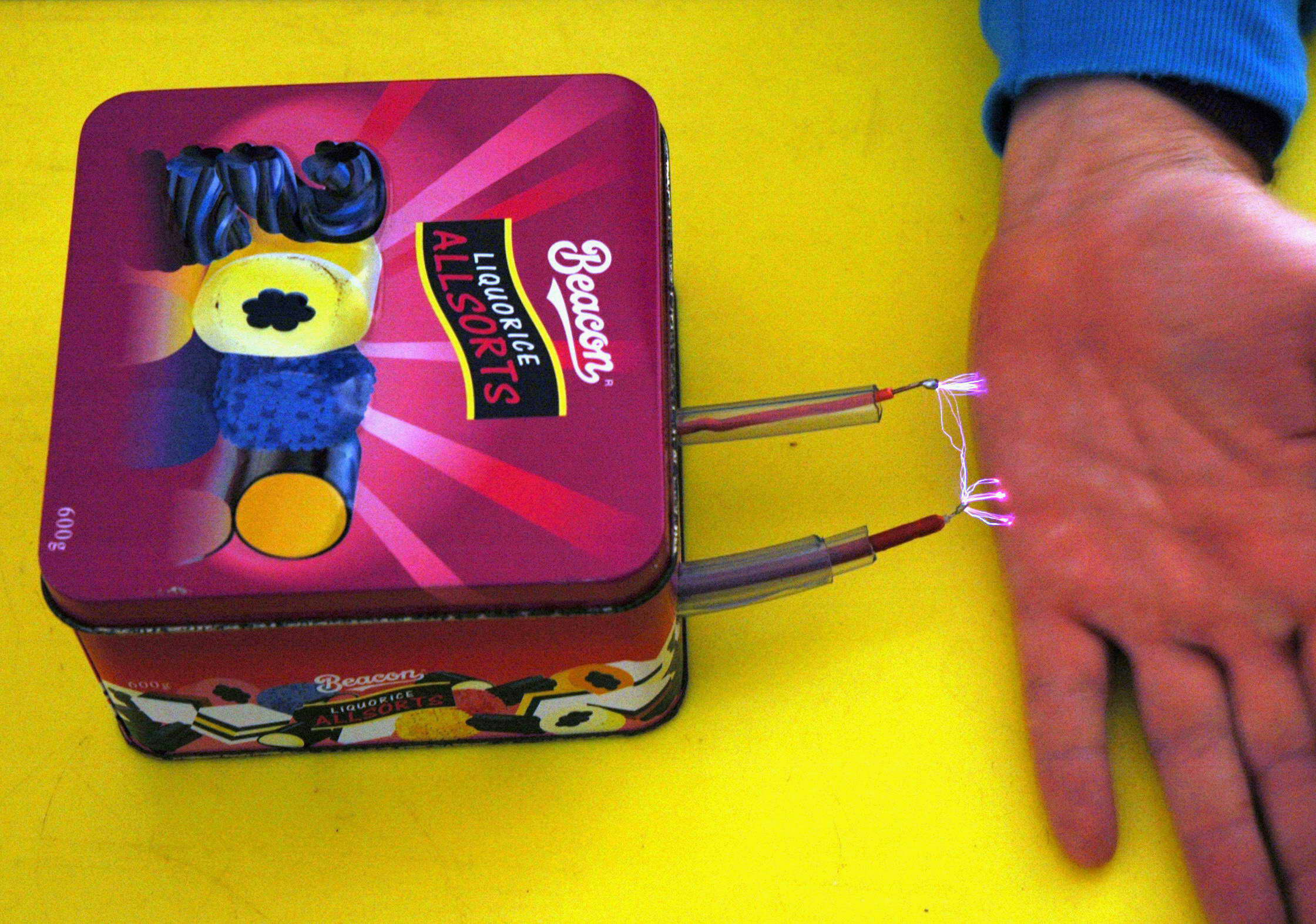
A spark should be a continuous line, jagged but without breaks. Right? So I thought too until you look closely at single sparks when you can see gaps.


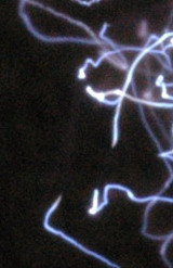
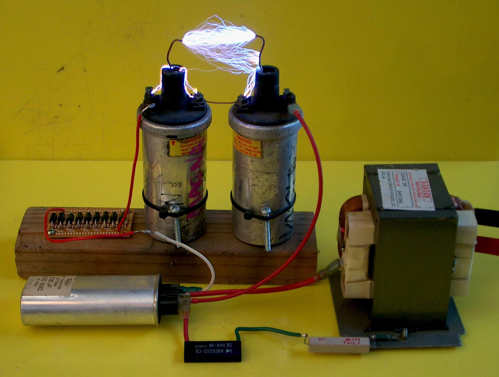
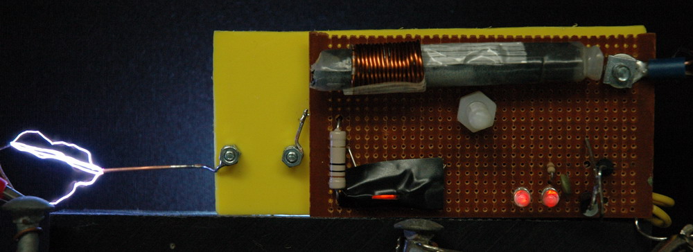
The photos above show sparks from my ignition coil setup with perhaps 10 sparks per second. This single brief impulse means that there is not a second spark going down the heated channel of the first. You can see gaps in the spark channel which is viewed here end on and magnified. Sometimes there is a hazy glow in the gap but often not.


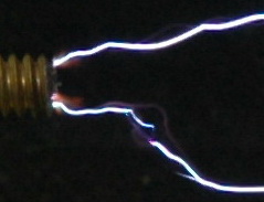
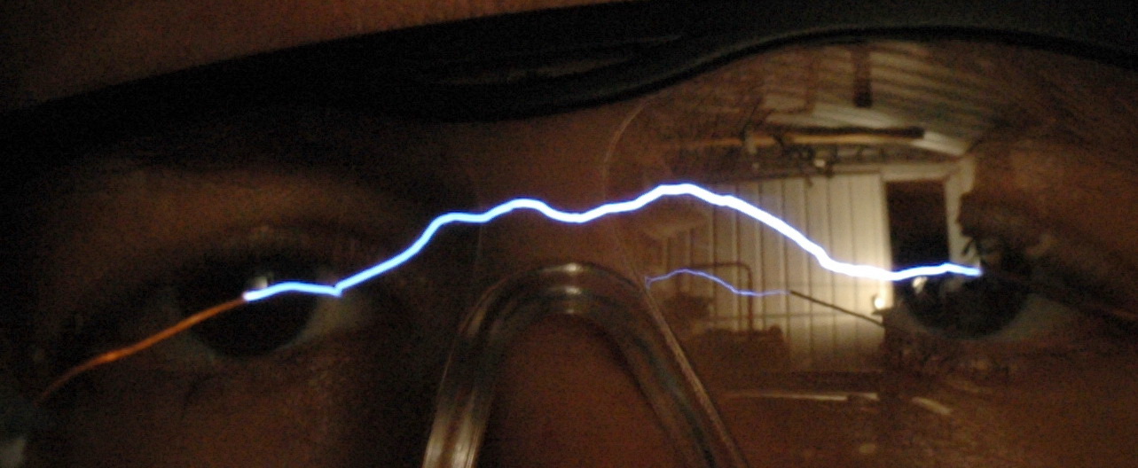
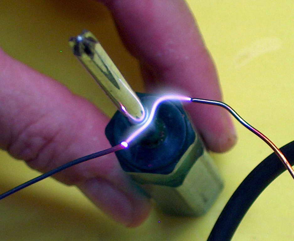
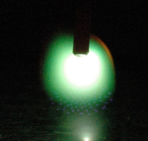
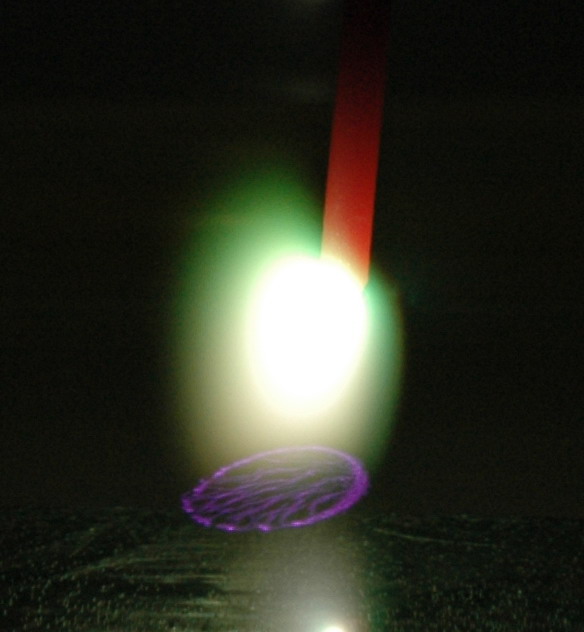
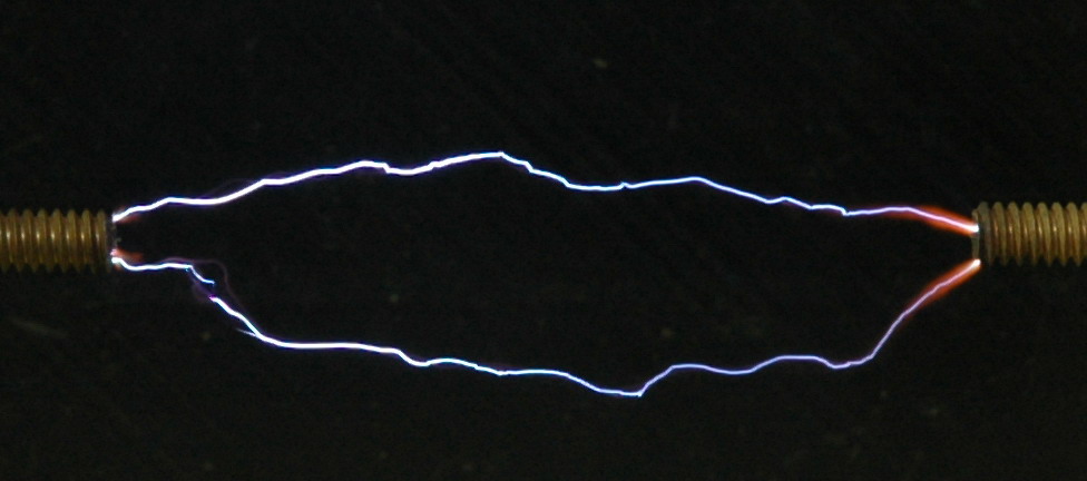
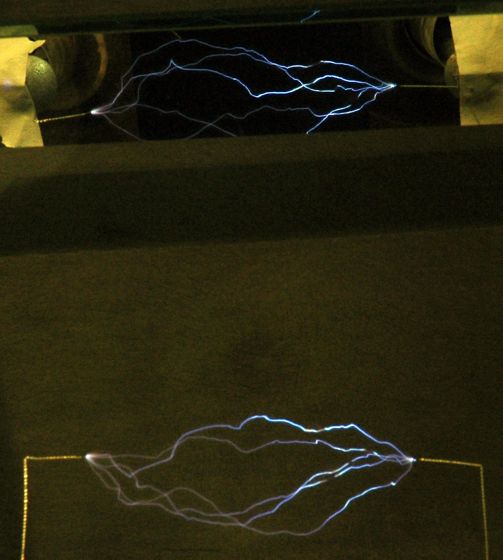
Here is another example with the magnified view. The left electrode is negative in this DC spark taken through my 300 kV diode so this is a negative side effect.


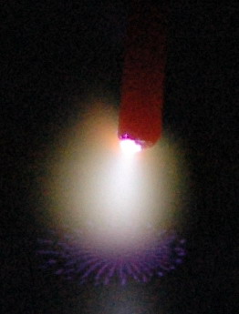
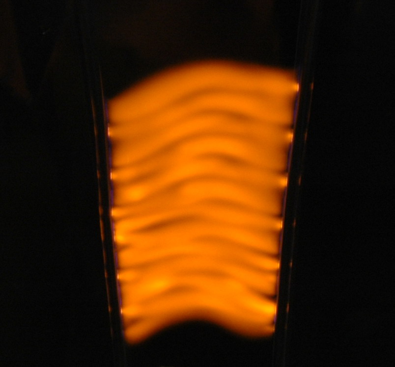
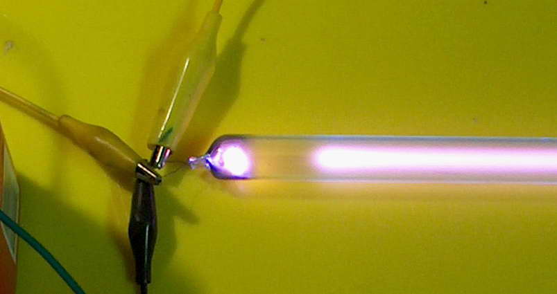
The photo above shows the Crooke’s space in a neon tube at reduced pressure. So there is a precedence for gaps in the spark channel.
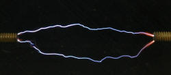
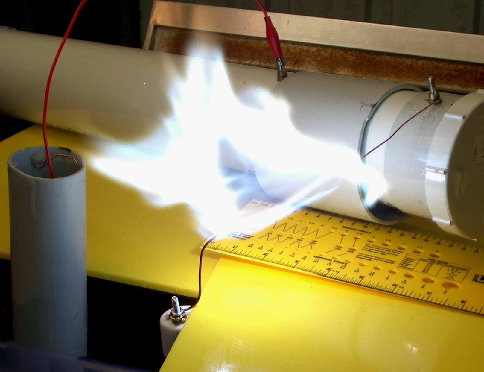
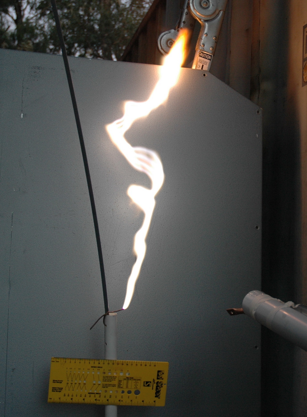
Sparks don’t have uniform brightness as well which may be a related effect. About one third of the negative end of the spark is brighter as well. Although this is a spark from a coil it is being driven by a DC pulse and can be regarded as polarized.


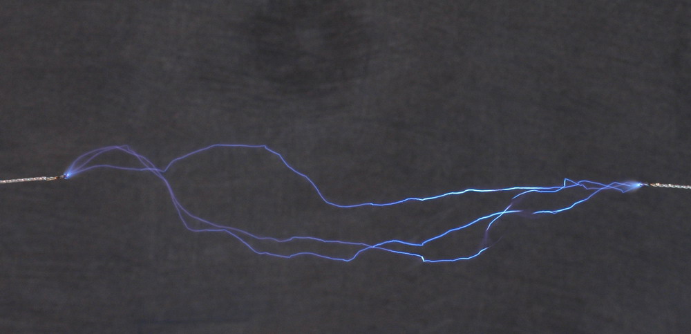
I therefore suspect that this is a feature of the spark structure, presumably analogous to the Crooke’s spaces seen in lower pressure discharges. Since you often see this with Tesla coils maybe the discharge is polarized there too.


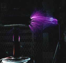
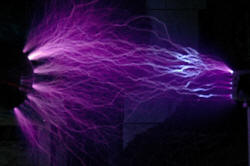
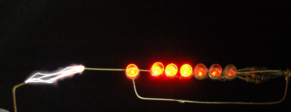
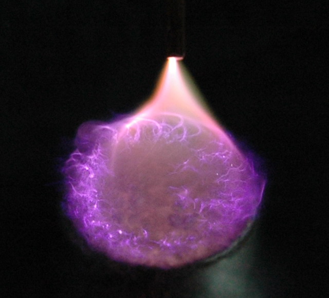
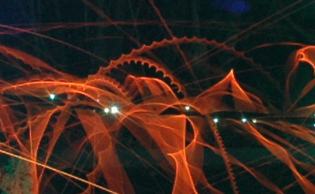
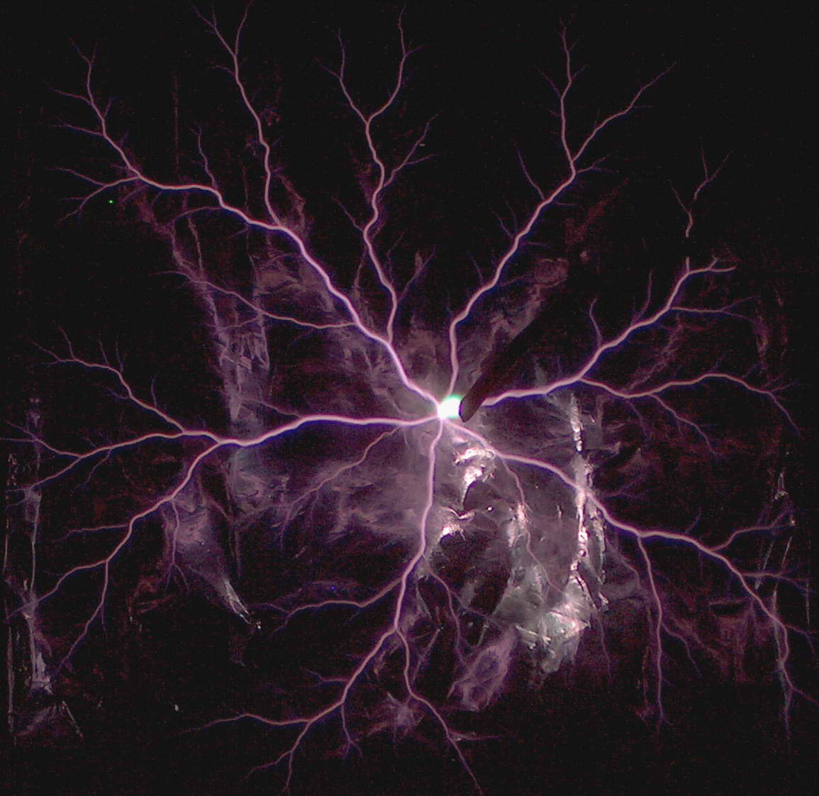
Above shows the bright area in the spark seen in a Tesla coil discharge. Generally seen when sparks are low power and purple rather than hot white. Sort of suggests that a Tesla coil sparks that only just connect are from a primarily positive discharge from the toroid.


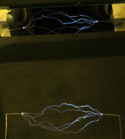
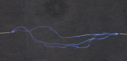
The spark above is viewed in two directions at the same time using a mirror at 90 degrees angle. 3 of the 5 sparks have gaps and they are present in both views. The negative end is brighter as well.

Also of interest:
A
Next topic:
A
Next Random topic:
A
Internal Links related:
A
External:
A Wiki
A Google+ post:
A 4HV post
Photo Date: 2006